Count down timer for my soccer club

Thread Starter

chrischrischris

Joined Feb 18, 2012
317
Thanks Bertus.
Sorry, I got my emitter/ collector terms back to front.
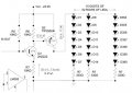
I originally had R7 as 470Ω 1/4W, however it was burning up. Bill mentioned it was because it was drawing too much current, hence change it to a 24KΩ 1/2W or a 43KΩ 1/4W. I ended up using a 47KΩ 1/4W as that's all I had on hand.

I've now changed it with a 10KΩ 1/2W and it doesn't seems to be getting hot, and the voltage in my TIP2955 collector is now up to 24V as I wanted. Is that OK to use a 10K?
 

bertus

Joined Apr 5, 2008
22,942
Hello,

I think the 10K value for R7 will be fine when you use the TIP147.
As the TIP2955 will need more base current, the value might need to be lowered.
With the value of 10K you might not get enough current for the display.(due to the lower gain of the TIP2955).

Bertus
 

Wendy

Joined Mar 24, 2008
23,797


Earlier I mentioned that Q2 had to be a super gain transistor (which is what Bertus is describing). You can not use a regular transistor, as the reduced gain is critical. There are several possible solutions here.

But first for something totally different.

To link to a previous image, click the previous image where it is the only thing on the screen, then put the URL between the {img]{/img] brackets, where the { is [. If I showed them directly then the site would try to interpret that as a img command, and puke. The internet address is the thing, you can do the same with offsite images, though we don't like it because the other site is totally out of our control (if it goes down so does the image).

I never use the attach command, as it never came up when I was learning how to use graphics on the site. :D

Anyhow...

Bill,
I connected one of the large digits to the new PWM circuit, however I found Q2 (please refer to #181 on page 19), doesn't deliver the full 24V out of the emitter. It only delivers 23V. (sorry, I don't know how to link to a jpg from a previous post, so I've attached it again below.

<snip>

I found:

1. When I make Q2 a TIP147, the emitter voltage is only 23V
2. When I make Q2 a TIP2955, the emitter voltage is 24V. However if I connect up a digit using the 2955, the voltage drops to about half and everything goes dim.

Any ideas/suggestions?

<snip>
I'm not sure what you mean by the emitter voltage of Q2 is only 23V, since that is directly connected to the power supply rail. Do you mean the emitter voltage of Q1 perhaps? If so this is normal. It is the on state for this circuit (digitally thinking). Some clarification here is needed.

When the comparator is on it shorts the base of Q1 to ground, which is the off state. Q1 turns off, which turns off Q2.

This circuit does have analog components, but it operates in purely digital modes. Where the analog comes in is to make sure the transistors turn on/off properly (as in completely).

When Q2 is purely on (and it does need to be a Darlington) it will drop 0.6V across the C-E, no way around it, as it is fundamental to how a Darlington works. It is the trade off for using a super-gain transistor. This means it will dissipate 0.6W at 1A (0.6V X 1A), which is not too bad, and easily taken care of with a small heat sink.

A factory built Darlington will have R6 included in the case, but you can make your own Darlington by putting a small PNP transistor in front of the TIP2955, and adding a separate R6.

Another thought just occurred, you may need to drop R5 to 3.3KΩ, as the gain of Q1 may not be sufficient. That or replace Q1 with a Darlington.
 
Last edited:

Thread Starter

chrischrischris

Joined Feb 18, 2012
317
Hi Bill.

I understand what you mean by the link. Thankyou.

In answer to your reply, yes I did change Q2 to a super gain tranisistor (Darlington?) - TIP147.
Q1 is still an 2N2222. Is that OK?

I was incorrect about saying the "emitter" voltage. I mean't to say "collector" voltage was lower. However, once I reduced the value of R7 from 47kΩ 1/4W to 10KΩ 1/2W, the collector voltage of the TIP147 ended up higher.

You mention a 0.6V drop across C-E. That's exactly what I measured - 23.4V. So it's the Darlington that drops it. I see.

Since it drops the voltage by 0.6V, hence the led intensity, can I therefore revert back to using a TIP2955 for Q2 instead? With the lower value of R7, there seems to be no voltage drop - it maintains at 24V.
 

Wendy

Joined Mar 24, 2008
23,797
The problem is gain. Remember I commented on being lucky? We are converting 53ma from Q1 (which is pushing the limits of that transistor) to 700ma for the LEDs.

It is a go/no go problem however, if it works it is good enough. Most electronic designs tend to be very conservative. I try for that myself.

The 430Ω should be getting quite hot, at around 1.2W (0.052A X 23.3V). It is a weakness I just noticed. Is it?

It may be the drive from Q1 is not all it should be. The basic design is sound, but some of the numbers may need tweaked (ie, resistors changed).
 

Thread Starter

chrischrischris

Joined Feb 18, 2012
317
Sorry Bill, I didn't update the jpg. R7 is not 430Ω anymore. You suggested to up it to 43KΩ. However this was the reason I think for the TIP2955 not working properly. I dropped it to 10KΩ and it seems to work.

My next question then is, in the circuit I've shown only 7 leds. However, this will be running all my digits (all 15 of them). My current seems to now be down to 700mA per digit, therefore overall max of 10.5Amps. I assume this circuit can therefore handle this current. Is that correct?

Also, should Q2 get fairly hot with this amount of current? If it does, how do I judge if it is too hot?
 

Wendy

Joined Mar 24, 2008
23,797
Power = Current X Voltage

1W = Hot, too hot to touch (a simple heatsink will go a long way for this)
½W = Warm, uncomfortable to touch (this is a good maximum)
¼W = Warm, easy to touch

43KΩ is a bit large. If you are trying for 700ma, then you will need 7ma for the base on a Darlington, 70ma for a conventional transistor on Q2. The less current, the less heat, which is what I am trying to balance. There will be heat, it is just where and how much.

The LEDs drop around 2.5VDC per LED? This works out to Qty 7 X 2.5V, or 17.5V, so your power supply voltage is adequate. R7 becomes the resistor controlling the exact current for the LEDs, assuming Q2 is turning on all the way.

Suggestion, practice calculating the currents you are feeding around. It isn't hard, and it will save some time in the long run. You sound like you are very close to the final design.
 

Thread Starter

chrischrischris

Joined Feb 18, 2012
317
I've now changed R7 to 10KΩ. My calculations is that the current is 2.34mA, 0.05W. Is that correct?

With Q2 (TIP2955), I measure the current as around 2mA at the base, 14mA at the collector and 17mA at the emitter. I assume the 2mA is 23.4V/10K. I assume the 17mA is the draw current based on 7 LEDs and a 330Ω resistor (my original aimed current of 15mA). The 14mA at the collector however, not sure how that's calculated using V=IR. Is it the 17mA - 2mA?

If I load up all digits (11.7Amps) does this seem as though it will handle it as is (see below)?
 

Attachments

Wendy

Joined Mar 24, 2008
23,797


Won't work well, I'm afraid. I had calculated the currents for R7 pretty closely. So lets go through the logic...

If you have 2.3ma through the base of Q2, and following the 1/10 rule of thumb for Q2 and saturation, you will get around 23ma or so, which is way too low.

You want 0.7A through the LEDs (worst case). This means you need 70ma through the base of Q2, you have a small fraction of that. For 70ma you need R7 to be 330Ω at 2W. If Q2 is a super-gain it can be around 7ma, and R7 can be a 3.3KΩ at ¼W. It is a case of TANSTAAFL I'm afraid.

The 0.6V a Darlington drops is not that much. Why are you fighting it so hard? You could add a 2N2907A (or equivalent) in front of the TIP2955 and make a discrete Darlington, if it is the parts issue you are fighting.
 

Thread Starter

chrischrischris

Joined Feb 18, 2012
317
Bill, I do have a Darlington - TIP147, and tried it. Unfortunately it dropped (as you guessed) 0.6V. Doesn't sound like much however this is the problem:
  • Aim was to deliver 780mA to each digit (i.e. run LEDs at 15mA each)
  • Current of each digit ended up measuring 700mA (i.e. 13.5mA each LED)
  • At 23.4V rather than 24V, current ends up 680mA (i.e. 13mA each LED)

The above doesn't sound like much, but I need these LEDs really bright when in direct sunlight, and I'm finding there are losses everywhere which will ultimately affect the intensity. I wish I could simply get say 25V out of my 24V/15A supply. 2 questions if I can:

1. Is there a way of getting say 25V, and less amps from a 24V/15amp supply? Then I can compensate for the 0.6V drop

2. You mentioned I want 0.7amps worst case through the resistors. Actually, when powering all digits, I need 15 digits x 0.7A = 10A to 11A. Are you aware of that?
 

Wendy

Joined Mar 24, 2008
23,797
2. You mentioned I want 0.7amps worst case through the resistors. Actually, when powering all digits, I need 15 digits x 0.7A = 10A to 11A. Are you aware of that?
Nope, though I should have been. This is the PWM switcher for every LED then? I was thinking for a single display. It is possible to have a separate transistor for every display to reduce this current requirement per transistor, but if you don't want to do this then it isn't that big of a deal. It is the design criteria I've been working with in my head for the last 20 or so posts though. :rolleyes: A mistake on my part, but there it is.

1. Is there a way of getting say 25V, and less amps from a 24V/15amp supply? Then I can compensate for the 0.6V drop
As I have said, it is part of using a Darlington. If you want to go with a MOSFET, which can handle large currents better, we can. If you want to use a BJT we can do that, but each comes with it's own set of problems, none insurmountable. 11A is starting to get into serious current.

Voltage losses are not a big deal, as long as they don't add to more than the Vcc and LEDs Vf drops combined. You are using green LEDs, which I am assuming are a Vf of 2.0 to 2.5V. Correct?

Going with a worst cast of 3.0V Vf it would still be 21V max. The 0.6V Darlington drop is still manageable. You would need separate wires for each display to the power supply, the resistance of the wire becomes a issue at 15A (adding a bit for overhead), which also has to take wire length into account. Each of them wind up at the power supply.

Just to clear it in my head;

Clock, 4 digits;
Thermometer, 2 digits;
Home Score, 2 digits (or is that 3 digits, as I'm not that familiar with Soccer);
Visitor Score, (same question).

Total: 10 digits (or is it 12?)

Sorry about that, this is one of the disadvantages of being in two continents on opposite sides of the earth designing. It is also why I'm working on teaching how to design this, you are more likely to be able to come up with local solutions from within.

If we use a separate transistor for each LED segment it is possible to make the BJT transistors current regulators. Just a thought. It would improve brightness characteristics a little (very little), but spread the currents around.
 

Thread Starter

chrischrischris

Joined Feb 18, 2012
317
You are using green LEDs, which I am assuming are a Vf of 2.0 to 2.5V. Correct?
I've measured the Vf of the LEDs to be an average of 2.74V. This ends up 19.18V max. So it is easily within limits. With 330Ω resistors, this ends up 15mA for each string. The ULN2003s however drops the voltage down a little.
You would need separate wires for each display to the power supply, the resistance of the wire becomes a issue at 15A
I'll be using 10 pin shrouded male headers for each digit and 2 cores of the 10 core ribbon would be supplying power to a single digit (common). So each digit will be supplied with power with separate wiring.
Clock - 4 digits, thermo - 2 digits, score 2 x 2 digits, count down timer - 4 digits (so 15 total).
If we use a separate transistor for each LED segment it is possible to make the BJT transistors current regulators.
.
Is it worth running the same circuit with a TIP2955 for each digit? Can Q1 handle that (and the rest of the circuit)?
 
Last edited:

Wendy

Joined Mar 24, 2008
23,797
Is it worth running the same circuit with a TIP2955 for each digit? Can Q1 handle that (and the rest of the circuit)?
Since you have made a design decision to go with a central source, lets stick with it for now.

Couple of points for clarification. BJTs amplify current, so if we want to amplify 5ma to 15A it requires a lot of gain. This is what we've been fighting so far.

MOSFETs are different, they take voltage and translate it into resistance. They handle high currents well, and drop much less heat because they go to very low resistances. Their disadvantage is they are very picky about their input voltages, but within their ranges they are clearly superior overall, and they are much more ESD sensitive than BJTs.

I'll draw another circuit based on the old design. At 15A and 0.6V drop the transistor will disapate around 10W, which is a major pain. The old 2N3055 with a good heatsink can easily handle this, but if we spread the currents around the individual wattages of the transistors can be brought way down.

Or we can go with a MOSFET.

I'll draw what I think you were trying to do, it will use more transistors to raise the current gain.

If the MOSFET option interests you tell me what part you can get, it should be a P-channel power MOSFET. There is a very good chance it will disapate less than a watt doing the same job, and there will be no voltage drop (no coincidence there).

I do not mind designing circuits, it is the same as doodling for me, so we can play around a bit.

For now I need to get my walk in, I've done 4 miles (M), 5.5 miles (W), and 2 miles (F) last week, and have gotten down to 219 pounds (starting from 235, and before that 265). I need to keep the pace up, don'tcha know.
 

Thread Starter

chrischrischris

Joined Feb 18, 2012
317
Hey, with all that walking and dropping pounds you must be getting fit as a fiddle now. That's excellent. Soon you'll be fit enough to join our soccer team!!!

Re-reading one of your previous posts:
You want 0.7A through the LEDs (worst case). This means you need 70ma through the base of Q2, you have a small fraction of that. For 70ma you need R7 to be 330Ω at 2W. If Q2 is a super-gain it can be around 7ma, and R7 can be a 3.3KΩ at ¼W.
Does this mean that options could be:
  1. Q2 = a TIP2955 single MOSFET requiring 70mA to run 0.7W, therefore to run 15 digits it would needs 15x70=1.05A. This would mean through Q1, R7 would need to be 24KΩ at 24W. Q1 couldn't handle this, nor is there a 24W resistor. Therefore this is not an option, OR
  2. Q2 = a MOSFET (TIP2955) for each digit (15 total) plus a Q1 (2N2222) for each MOSFET (15 total), of which each has an R7 of 330Ω at 1/4W (15 in total), OR
  3. A single Darlington requiring 7mA per digit. So to run 15 digits it would have 105mA at the base. This would need R7 to be at least 4.7KΩ at 2W. Disadvantage - drops 0.6V.

I supposed the simplest circuit is what I'm looking for with the least voltage drop at this stage.

The MOSFET I've got is a 100V 15A 90W PNP transistor in a SOT-93 package.
http://www.rockby.com.au/catresults.cfm?imageField2.x=0&imageField2.y=0&stock_no=40068
If however I need more than one, I can source them OS for around $1 for a TO-220 package. Can the circuit be changed to get sufficient gain to run a single MOSFET? Or is this not a good idea/not possible?
 
Last edited:

Wendy

Joined Mar 24, 2008
23,797
The only reservation I have about the MOSFET you are looking at is the current is too close to spec. You should have around double the current you will use, though a 20A will work.

MOSFETs are a different beast, they come in N-Channel or P-Channel. N-Channel are more common and have better specs, but in this case we need the P-Channel variety. NPN and PNP are strictly BJTs.

Due to their efficiency in switching you will only need a small heat sink. Truth, I am not as strong with MOSFETs as I am with transistors, but I'm learning.

Here are the two schematics, both are meant to be single sources for the PWM. The first is the final schematic of the BJT version, and I have added 2 more transistors (1 more?) to up the current gain. I have listed the wattages each transistor will dissipate, they will each need their own heat sink. The TIP2955 and TIP3055 have a lot of power rating (which you need), but their gains are not very good, Darlington pairs compensate nicely for this.

With the second schematic (MOSFET) Q1 and Q2 can be low power switchers, such as the 2N2222A and 2N2907A or equivalent. They should run very cool. Q3 will get warm, but that should be it. Just in case, add a light heatsink though. R3 should be as physically/electrically close to the gate as possible.

Unless otherwise designated, all resistors are ¼W.


Attachments

Last edited:

Thread Starter

chrischrischris

Joined Feb 18, 2012
317
Sorry, just 3 questions if I can:

  1. In the 1st diagram, is Q1 and Q2 an NPN such as 2N2222, and Q3 and Q4 a Darlington (such as TIP147)?
  2. In the 2nd diagram, I assume Q3 is the TIP2955?
  3. I was reading up on MOSFETs today and found that even 60V 27A MOSFETs are common and cheap. I read somewhere also something about hooking them up in parallel to distribute the current. Is this an option?

By the way, I just tested my 24V 15A supply. It measures 24.73V. This means I won't feel the 0.6V drop from the Darlingtons, so if this is a better option, I'll go with it. By the way the TIP147 seems to be only rated 10Amps. Is that correct? Oops, that's 4 questions...
 
Last edited:

Wendy

Joined Mar 24, 2008
23,797
1. It can be a off the shelf Darlington, or it can be a 2N2222 and a TIP3055.

2. Second diagram, Q3 is a new beast to you, a MOSFET. I have labeled the pins D, S, and G for Drain, Source, and Gate, which is in the datasheet. Note the symbol is very different, and the direction of the arrow defines the exact type, P-Channel or N-Channel. If you want a quick article on them read my LED, 555 article, chapter 10.

3. Yes. But all you need is one good one.

3.5 You wouldn't notice the Darlingtons in any case. I am not familiar with the TIP147, but I believe the TIP2955 is more than capable.
 

Thread Starter

chrischrischris

Joined Feb 18, 2012
317
I just tried diagram 1, but used a 2N2222 as Q2. The transistor was burning up.
I'll replace Q2 with the 3055 tomorrow and see how it goes.

On a completely different question,
At work we are buying a cabinet to house 16 laptops. I was trying to work out how many amps it would draw (ie. do I need a 10amp or 15amp socket).

Our laptops have 19.5V, 12.3A AC adapters to charge them. Under the laptop is the same specifications. This ends up close to 240W.

Does this mean that at 240AC supply, it is 240W=240VxI, therefore I = 1amp?

I tried to measure the current draw from one tonight and seemed to be only 350mA. If this is the case, then 16 would be 16x350 = 5.6A. Is my logic correct?
 
Top