Count down timer for my soccer club

Thread Starter

chrischrischris

Joined Feb 18, 2012
317
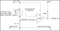
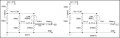
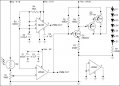
I've re-drawn the 555/LM393 PWM circuit now based on the new 555 layout suggested earlier. Current layout - see below:


1.
Could you tell me why in the above circuit R7 (470Ω resistor between Q1 emitter and ground) is burning up. Is it the right value? If I change it to 10K, it seems to work just as well without the heat.

2.
I've done a stack of measurements so I can start to work out the correct LED intensity via the LM393 and R1 & R2 combination, but I don't know how to do the calculations. These are the figures I've got:

  • 555 supply voltage = 5.18
  • R1=1kΩ, R2=33KΩ (didn't have a 27KΩ), electrolytic = 0.237uF (2 x 0.47) in series) - didn't have a 0.1uF
  • Calculated frequency = 111 (yes a bit low)
  • 555, pin 2 triangular wave measures 1.7V to 3.4V - (this lines up with 1/3V and 2/3V)
  • Vcc average (measured) from 555 pin 2 = 2.6V - (again lines up with 1/2 Vcc of 5.18)
  • LM393 is therefore fed 2.6V at pin 6 (reference voltage)

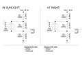
From the above I now need to calculate what voltage I need at the LM393 pin 5 so I get the LED minimum and maximum brightness levels I want. This is what I have:

  • In direct sunlight I measure the LDR resistance as 300Ω
  • Under the artificial lights (night) it measured 200KΩ
Now I'm not sure how to calculate the resistance I need on the 5.18V supply. I don't want the LEDs to ever turn off, and I need them full brightness.

3.
In the PWM circuit above, I measured the Vcc across the LEDs ranging from 19.17V to 0V. However, 4.88V is the minimum that seemed to "look ok". These figures corresponded to 14mA to 4mA (min acceptable).

Can someone please help here.
 

Attachments

Last edited:

Wendy

Joined Mar 24, 2008
23,797
I see the problem. Here, let me illustrate it...


See?

This is why I was hoping you would use a supergain transistor such as a Darlington. Where a regular transistor needs 1/10 the collector current, a Darlington needs less than 1/100 the current.

Raise R7 to 24KΩ ½W. It could be even larger, but I am being conservative. If you want to go with 43KΩ ¼W it would probably work.

You are going to have a pretty good base in DC electronics and transistor theory before this is done.

.
 

Attachments

Thread Starter

chrischrischris

Joined Feb 18, 2012
317
Hi Bill.
Just trying to balance the LDR now.
I need to select the correct R1 (and layout) to have the voltage going into pin 5 of the LM393 vary from 2.6V (full strength LED brightness) to 1.7V (looks about right for night time).

If you work it out, could you tell me how you do the calculations so I can then go away and fine tune it. See suggested part circuit below.


Attachments

Thread Starter

chrischrischris

Joined Feb 18, 2012
317
Yes it is.

I put my hand fully over the LDR - the 7 LEDs I had connected turned off.

I then pulled my hand away a bit allowing more light over it and the LEDs turned back on dimmly.

I kept moving back and forward until I got the LEDs dim, but not blinking. My "guess" of how bright I would need them at night.

At the same time I measured the voltage going into pin 5 of the LM393. It was around 1.7V.

At 2.7V (i.e. 1/2 of Vcc), they are at their brightest (which is what I need for day time).

Is my method correct? If so, how can I adjust the circuit to get these voltages?
 

Wendy

Joined Mar 24, 2008
23,797
This is a basic voltage divider problem Since I can assume the LDR is fully on when it is 2.6VDC this sets one end, the other end is trickier. It is probably best if you use a variable resistor for R1. However, I'll go through the math to show how it is done.

Actually, it has been a very long day. I set the problem up, when I am more awake I'll solve it, unless you beat me to it. R2 is the LDR, there is only one set of values for R1 and R3.


Attachments

Thread Starter

chrischrischris

Joined Feb 18, 2012
317
Bill.

To range from 1.7V to 2.6V with the LDR, I've designed the circuit below. Could you check it please.

One thing I'm not sure of is the current in the "day" setup. The 100K & 375K setup may not let through enough current. I work out that the 0.9V is at 0.004mA.

Calculations via excel:
https://dl.dropbox.com/u/80130564/PWM%20calculation.xls

Actually looking at the circuit above, I probably can eliminate the 2 x 100Ω and change the values of the other resistors to compensate - if you think the circuit might work.

Sketch amended. See next note.
 

Attachments

Last edited:

Thread Starter

chrischrischris

Joined Feb 18, 2012
317
I looked back on my circuit above and realised I got the resistance calculation back to front.

I've tried to simplify it as well (see below).
However, I'm not sure if I've "ADDED" the voltages together correctly.
Also, I'm still not sure if the really low mA makes any difference going into the transistors.

Please let me know if the circuit below will work. Thanks in advance.


Attachments

Thread Starter

chrischrischris

Joined Feb 18, 2012
317
Hi "takao".
I would but my elec knowledge is limited, and I'm trying to design this project without any programming.

I tried my voltage dividers above, and when separate, I do get the correct voltages. Where I'm unstuck is how to "add" the two separate voltages.
 

Wendy

Joined Mar 24, 2008
23,797
Chris, I apologize, I set the problem up wrong. Once I realized what I had done it became easy, so easy I didn't need math to solve it.

First the setup.


Then the math, simplified.

Lets look at the ratios,
Bright 1.7/5.18 = 32.8% ≈ 33%
Dim... 2.6/5.18 = 50.2% ≈ 50%

If you understand the design of the PWM circuit 33% is full range, while 50% is exactly mid range.

If the LDR is 200KΩ dark, and that is 1/3 of the total, then the other two resistor need to be 200KΩ.

Going with the formula I showed...

Bright: (200KΩ * 5.18V) / (200KΩ + 300Ω + 200KΩ) ≈ 2.59V
Dim : (200KΩ * 5.18V) / (200KΩ + 200KΩ + 200KΩ) ≈ 1.73V

Again, sorry about that.

I would still use a 150KΩ resistor and a 100KΩ pot in series for R3, for a fine tweak of the dark value.

.
 

Attachments

Thread Starter

chrischrischris

Joined Feb 18, 2012
317
Hi Bill.
Such as easy circuit.

However one problem.
If the value of the LDR goes higher than 200K (i.e. the LDR's range can go as high as 2.5MΩ if totally dark), then the voltage drops below 1.7V and the lights start to flicker then eventually if low enough turn off.

On my previous circuits above, I was trying to set a minimum voltage of 1.7 and then have the LDR adjust for the remaining 0.9V to reach the 2.6V.

Is this possible? If so, how? Can your circuit do this somehow? Or can the circuit I started (go back a couple of replies) achieve this?
 

Wendy

Joined Mar 24, 2008
23,797
Let's try something empirical first, if it doesn't work we can go backwards a little. Put a 220KΩ - 470KΩ (a 1MΩ pot?) resistor in parallel with the LDR, it will force a maximum value. The difference to the LDR between 220KΩ and 2.5MΩ to the LDR is not that great, but it force a set maximum value for the voltage divider.
 
Last edited:

Thread Starter

chrischrischris

Joined Feb 18, 2012
317
After posting my reply, on the way to work I was thinking exactly the same thing - adding 1.7V in parallel so that it never dropped lower. I'll try that later tonight.
 

Thread Starter

chrischrischris

Joined Feb 18, 2012
317
Let's try something empirical first, if it doesn't work we can go backwards a little. Put a 220KΩ - 470KΩ (a 1MΩ pot?) resistor in parallel with the LDR, it will force a maximum value. The difference to the LDR between 220KΩ and 2.5MΩ to the LDR is not that great, but it force a set maximum value for the voltage divider.
Bill, I've been experimenting last 2 weeks. I found:


  1. The minimum voltage I think I need is 1.87V for the LEDs to look ok at night (dim setting). The 1.73V I was testing, I found to be right at the bottom of the triangular wave - so just a bit too low.


  • The maximum voltage (to get 100% brightness) is actually just a little over 3.45V. I'm not sure why because I assumed the comparator would be looking for 5.18/2=2.59V for full strength. What tha? Is something gobbling up voltage somewhere?

So I'm finding it hard getting a voltage divider combination to achieve 1.73V to 3.45V, and maintain a 1.73V minimum at all times. What do you suggest?
 

Wendy

Joined Mar 24, 2008
23,797
I don't have time at the moment to draw it, but had suggested using pots to allow adjustment of both ends. It would require a 1MΩ pot and a 200KΩ pot, one would be for the max and the other for minimum, with a specific procedure to minimize interaction between the two settings while adjusting them.

Let me take the time to draw it before making assumptions, but I can describe the procedure. First, use the 200KΩ in series with the 100KΩ resistor (R4 is the 200KΩ pot, R5 is the 100KΩ resistor) at max light to adjust for max brightness. The LDR will be at its minimum value. The voltage should be 2/3 Vcc or slightly higher.

Then, at minimum light level, adjust the 1MΩ pot (R2, the LDR is R6) in parallel with the LDR for the LED level you want. It should be somewhere around ½ Vcc, but the exact voltage is not important. Vcc is the 5.18V.

Always adjust R4 (max LED level) first, then R2 (min LED level) second to minimize interaction between the two. It should be relatively straight forward.


There are times pots really are the best way to make a circuit where you need to tweak the values.

You might think of making a simple light meter with a similar LDR and a ohm meter to work on this.

.
 

Attachments

Last edited:

Thread Starter

chrischrischris

Joined Feb 18, 2012
317
Bill, I tried the layout, but found with R1 at 220K and R4+R5 maxed out to 300K, the best I could get was 3V out (rather than 3.45 needed).

I then adjusted the R2+R3 combination to achieve 310K, which gave me my 1.87V out - good. So it was only 1 end that didn't work.

I then fiddled the values & your method and I think I got it. Can you check if it makes sense:


Attachments

Wendy

Joined Mar 24, 2008
23,797
Looks good from here, what works, works.

One of the reasons I like the pots is if you ever duplicate the design there is no guarentee the LDS will respond exactly the same.
 

Thread Starter

chrischrischris

Joined Feb 18, 2012
317
Bill,
I connected one of the large digits to the new PWM circuit, however I found Q2 (please refer to #181 on page 19), doesn't deliver the full 24V out of the emitter. It only delivers 23V. (sorry, I don't know how to link to a jpg from a previous post, so I've attached it again below.

PWM_5.jpg

I found:

1. When I make Q2 a TIP147, the emitter voltage is only 23V
2. When I make Q2 a TIP2955, the emitter voltage is 24V. However if I connect up a digit using the 2955, the voltage drops to about half and everything goes dim.

Any ideas/suggestions?

TIP147 Darlington: http://pdf1.alldatasheet.com/datasheet-pdf/view/54795/FAIRCHILD/TIP147.html
TIP2955 Power transistor:http://pdf1.alldatasheet.com/datasheet-pdf/view/2776/MOSPEC/TIP2955.html
 

bertus

Joined Apr 5, 2008
22,941
Hello,

The emitter voltage of the transistor will be equal to the power supply voltage.
The collector of the transistor will be different for the shown transistors.
The TIP 147 is a Darlington transistor wich has a very high gain and a higher saturation voltage, so the collector voltage will be lower.
The TIP 2955 is a single transistor with low gain and a lower saturation voltage.
It will need more base current to reach the saturation voltage due to the lower gain.

Bertus
 
Top