No, they just don't fail as easy. A good thing overall. I'll put the other schematic up later tomorrow. I should have known better, a verbal description just doesn't cut it.
Bill,
due to the heat load on the 2N2907s, and your comment about PNP's getting hot as compared to NPNs, I've tried to preserver with 2003a's with a change.
I found that connecting the 7107 outputs straight to the 2003a just wouldn't switch correctly. With my limited knowledge, I'm guessing that for some reason, the 7107 outputs are not sufficient for cleanly switching the 2003 directly - tends to stay partially low. Maybe pull-up resistors would help, but I couldn't work it out.
I don't know if this is ok...
Via 10k resistors I ran the 7107 signals to the base of the 2907s. I connected all the collectors to the 5V that supplies the 7107. I then ran the emitters into the input of the 2003a. This works perfectly without any heat. Is this OK?
Now before you say it, I think I should use NPNs instead of PNPs as in the small sketch above. Unfortunately I still don't really understand how transistors work. I found if I reversed the 2907s (collector/emitter) the circuit still worked. If I reversed the 2222s (collector/emitter) it didn't work. Is it easy to explain why?
Bill, I'm now onto the PWM circuit.
I've had a good read of your LEDs, 555, PWMs... great info.
I've build the circuit you included in the previous post with the 555 and LM393 (which I bought today) - ie. the circuit similar to figure 5.3.
I've only got on hand a 5K pot and 10K pot, so I put the 5K pot on the 555 and the 10K on the 393. As I rotated the pot on the comparitor, I see a change in the intensity of the led. Changing the 555 pot, the change is really slight. Can you explain what's happening hear as I don't fully get it.
Also, where to from here.
(PS. In your blog, in the notes for Figure 5.3 you mention about the pull up resistor required for the LM393 as well as the LM339 quad comparitor. However there isn't an LM339 in the circuit. Is that correct?)
What you are changing with the 555 pot is the base frequency. This can be useful if two frequencies (PWM base frequency and multiplex) are beating together (also known as aliasing). This can cause a slow pulsing of the intensity that is not related to the PWM or anything else. You can change the PWM base frequency until this is not the case.
The pot going into the LM393 is simply a voltage source, and can be replaced with a voltage instead. The 555 triangle wave sets the range, 1/3 to 2/3 Vcc. This can easily be replaced with a simple LDR (light dependent resistor, or photocell) circuit.
The LM393 and LM339 are cousins, very close to each other, and given some rewiring to allow for the different pinouts, interchangeable. One has 4 comparators in one package (LM339), while the other has two (LM393).
I am going to write a tutorial on transistors simplified, expanding on chapter 10 of the LEDs article. In many ways it will be repetitious, covering much the same ground. If you haven't read this chapter it is worth going over, it would have helped you with your project.
OK, using my Figure 5.3 out of my LEDs, 555s, Flashers, and Light Chasers I have come up with this. It is a fundamental concept circuit, details will need tweaked.
Bill, following your suggestion in the above reply, I've breadboarded the circuit. I need to now take this to the next level and run it with an LDR.
All my 16inch digits (15 in total) are run with 24V DV, each running at around 800mA (total around 12amps). They're all common anode. It's the common anode I'd like to interrupt with the PWM circuit to adjust the brightness between day and night.
Can I now somehow use the LDR to auto adjust the voltage to the common anode group. I'm not sure how to progress from here.
I just got home from work, so I'll give the quick description followed by more in depth in about 9 hours.
The photocell with a resistor will generate a voltage. Since the PWM has a voltage in it is a matter of matching the adjustment to the light level, probably with a pot. If you need several light levels then it gets slightly more complex.
The grounds of your LED displays will connect to a transistor, probably a Logic Level MOSFET (due to 6V drive on the power). 12 V power supplies mean you can use a conventional MOSFET (due to voltage). It is this transistor you will PWM.
Thanks Bill. No problems - reply only when your ready.
When your coming up with a solution, is it possible (or easy enough) to make it auto-vary pending the light level - i.e. not just 2 or 3 levels, but rather something that measures that voltage variation and dims accordingly. If not, don't worry. When I know how to do 2 or more variations, I can always add a few more - so it's "gradual" and not noticeable.
Up for a short while, loo break. The problem is one of curves, I can make a simple circuit, but the intensity to light level curve may not match what you want. I can give you two setpoints, but the the intensity between the two setpoints is anyones guess.
Via 10k resistors I ran the 7107 signals to the base of the 2907s. I connected all the collectors to the 5V that supplies the 7107. I then ran the emitters into the input of the 2003a. This works perfectly without any heat. Is this OK?
If what you hooked up works, you're probably fine.
Now before you say it, I think I should use NPNs instead of PNPs as in the small sketch above. Unfortunately I still don't really understand how transistors work. I found if I reversed the 2907s (collector/emitter) the circuit still worked. If I reversed the 2222s (collector/emitter) it didn't work. Is it easy to explain why?
Okay, so note that the ULN2003 and UDN2981/2 sink or source current respectively when their input is pulled HIGH. This is great for LED driver ICs like the CD4511 because they output a HIGH signal when it turns on a segment.
The ICL7107 works in the opposite direction. It turns on a segment by SINKING current and does this by pulling it LOW. If you're segments didn't require a higher voltage and current, you could connect them directly to your CA display. Since this is not the case, you need to something that enables you to sink large currents and voltages. A 7407 as shown in the datasheet works for slightly higher currents and voltages, but not enough for your digits. Some interesting facts I've learned researching this.
The 7407 is a non-inverting open collector. This means when a low signal is received on the input, the output is pulled low and sinks current. When a high signal is received, the output isn't pulled at all and no current flows.
The 2003 is a inverting open collector. This means that when a high signal is received on the input, the output is pulled low and sinks current. When a low signal is received, the output isn't pulled at all and no current flows.
I couldn't find any non-inverting open collectors that would handle the power requirements of your digits. Therefore, I suggest using an inverter with the 2003. In effect, when the 7107 wants to turn on a segment, it sends a low signal (2.5V to 0V). We then want to turn that low signal into a high signal before it goes into the 2003.
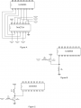
I've attached some ideas on interfacing between the ICL7107 and the ULN2003. I haven't tested these, but they are based on my limited knowledge of transistors and research on the web. I've ensured the 2003 input is always low when the 7107 output is high. I've shown a PNP, NPN, and inverter IC.
Bill, could I ask you to review my ideas as well as Chris's current hook up and comment?
I'm backing up to basics. A CD4009 may not be good for this application, how much current does each segment require? In trying to use a UL2003 I suspect we are twisting this to a level of complexity where normal transistor would work as well.
Sorry elec mech, I will have to draw a circuit showing the 2003 innerds to wrap my head around it. I've been running on short sleep, which is not helping (dang 3rd shift).
CMOS and TTL gates generally do not make good drivers. Reading the data sheet on a 4009 I think they are saying it is designed for it, but I haven't seen any output current specs yet. I'm probably missing them.
I'm going to have to read up on the 7107 to understand what it's outputs are doing, since this chip has a ±5V power supply.
I apologize, but I'll try some sleep first, then work on it.
Your explanation of the ULN2003 and UDN2981/2 sinking and sourcing current was well explained. It makes good sense. I ended up using a 10K resistor at the base of each transistor (see schematic below).View attachment temperature circuit.pdf
The reason I used the 4009 was to create a negative supply from the 5V supply I am using. The circuit is outlined in the specification sheets for the 7107 - http://www.maxim-ic.com/datasheet/index.mvp/id/1353
See figure 15 for my temp layout and figure 10 for the negative supply via the 4009.
Yes, sleep is good. It's 1:30 am here - I'll head off too.
Bill, I've now got my 4 pcb's working - 1. count-down timer, 2. dual score, 3. clock & 4 temperature. All have worked with the 16" digits.
I've also now breadboarded the PWM circuit on the previous page (2nd one with the LDR and 1MΩ). I just haven't added R9 and Q3 to connect them to a digit as yet. I'm not really sure that Q3 is. It looks like a cross between a variable resistor and transistor - does that make it a tranristor?
Without out however, using R5 and the LDR, when I cover the LDR it does go brighter (the single led I have hooked up) but not enough. There needs to be more variation in intensity.
As for non-linear change, is there an easy way to tackle that?
(PS. Just found out that symbol in Volume 5 of this site - transistor with n-channel enhancement - whatever that is. I assume a MOSFET)
I profusely apologize for not getting back sooner, seems like what free time is being eaten by kids, pets, local friends, and medical issues. Add third shift to that and I over committed.
Instead of giving you half baked schematics, lets go through what is happening with the parts. It will give you specific directions to go.
When going through college almost 40 years ago I thought it was interesting the holes in my knowledge the courses filled, I had been a hobbiest for several years. I knew I didn't know it all, but the things I didn't know surprised me.
LDR
You are probably very familiar with this part, but just in case I'll go through the basics. It is a variable resistor that depends on light. At full brightness it goes down to several hundred ohms, at dark it is several megohms, maybe more. It is extremely repeatable. You can measure its ohmage as specific light levels, and then use math to design around it (which is good news).
I used it as part of a voltage divider. More on this in a bit.
PWM
The PWM circuit I showed in Figure 5.3 is very linear, extremely predictable, and completely independent of the frequency, all good points. The voltage divider in this circuit made up of R4, R5, and R6 can be replace with other voltage dividers or voltage sources. The PWM responds linearly between 1/3 Vcc to 2/3 Vcc.
I would use this circuit verbatum to find out what the PWM levels you need for light levels on your board, done empirically. Basically you will create a voltage to light intensity chart. Two point on the curve is easy, 3 points or more gets more complex. I suspect knowing your background you are bit better at math than I (an understatement).
The basic light level to voltage converter
OK, lets go through the basics.
Example 1 is a simple on/off setup. I have no clue what the setpoints are, and don't care that much. It will likely work first time, though there is always the chance I will have to tweak the value of R1. Basically the voltage is fed into a circuit that will trigger at a specific setpoint (called a Schmitt Trigger).
Example 2 will allow 1 set point, I adjust the light level into LDR1, then adjust R1 to match what I want. Not precision, but repeatable.
Example 3 will adjust voltage basic curves. It works best if you know the values of LDR1 for the light levels you want. You can remove R3 or R4 to adjust curves, and the idea is to use Ohms Law to create the voltage you want for a specific light level. The math is not especially hairy, just tedious.
I put the LDR on top. This will mean the voltage goes up as the light levels increase. If I put the LDR on bottom will make the voltage go down as light levels increase. Overall, it is simple, the devil is in the details.
I am assuming you now know Ohms Law and how it applies to voltage dividers. If this isn't the case just let me know, and we'll go over it. Any other questions are also welcome.
Adapting PWM to the displays
I covered this in an earlier post, but it may not be clear. From your last post it sounds like you have it though, do we need to go over it?
I can modify the print to use a BJT (a normal transistor). MOSFETs really require 10V on the gate, that and ESD sensitivity is their main disadvantages. In most ways that count they are a superior component.
Bill, remember your doing "me" the favour, so I have no expectations - I can only give thanks for "any" help you offer.
Since I've been concentrating on the other 4 components of this projects, as well as building the 16 inch digits, I haven't been held up with progress on this project to date.
I do basically understand how an LDR works and its use in the circuit. When you mentioned however that the circuit works linear between 1/3 and 2/3 Vcc, I assume this is to the way the 555 works - I bought a booklet on it reading about how the caps hold and dropped the voltage.
Ohms law and maths - no probs at all.
Some figures I measured a while back:
1. Digit run on 24V is clearly visible in full sunlight (approx. 800mA draw)
2. Digit at night via 16.8V (i.e. using a 150Ω 1/2 W resistor) look perfect
3. LDR reading in full sunlight = 300Ω
4. LDR reading under artificial lights at night = 200KΩ
(I'll check again tonight under lights what the exact figure is).
My question now:
1.
In your 2nd diagram on page 10 of this post, you used a mosfet to drive the grounded side of one segment of a digit. Looking at my circuit above, I'm wanting to alter the anode side (common anode digits). Hence I'd like the PWM to control the anode supply to all the segments and all the digits in one hit if possible. That's 15 digits at 780mA max each = 12A worth. Possible? If so how.
2.
When you mentioned that the voltage was linear between 1/2 and 2/3 Vcc, does than mean that I just have to have a bigger upper and lower resistance limit and use only the section between the 1/2 & 2/3? I'm not exactly sure what I'm graphing yet to achieve the intensities. I need a hand to "start off" - an rough made up example.
On another question however, I've just been verifying the current draw on my leds and the numbers don't add up to the actual. Could anyone please explain why.
Theoretical calculated values are:
* Source voltage 24V
* Vf = 2.7V
* Preferred led forward current = 15mA
* 7 leds linked in series with a resistor
Maths:
24V - (7 x 2.7V) = 5.1
V=IR, therefore R=V/I=5.1/0.015 = 340Ω
(use of 330Ω close enough)
Measured values:
* Source voltage 24.05V
* Vf across 7 leds = 19.10, therefore 2.73V across each
* Current draw measured with my meter between 14 and 15mA
Problem:
I then measured the current draw from my 7 segment digit (total 52 sets of these 7 led/resistor combinations - in parallel). As each string should be 15mA, 52 in parallel should be 15x52 = 780mA. I measured it with my meter and it reads only 630mA. Where have I lost 150mA? Does this mean I should use small resistors in order to have the LEDs run at 15mA?
It is hard to say exactly where the theory is breaking down, I'll think on it, but there are a couple of maxims I use with this kind of work.
Negligible variations aren't. They tend to add up in unexpected ways.
Meters aren't perfect. They are very good, especially with voltage measurements, but current measurements can be more of a problem. For current most of them use a built in resistor (a shunt) and measure the voltage across the shunt. It is important to remember that the shunt is still a resistor however, and interacts with the circuit. There are active circuits that can be much more precision, and when it is important you can add them into circuits (they will only be in very expensive meters). A better way to measure current many times is to measure the voltage across a known resistance, this is equivalent to a shunt, but the resistor does not go away when you disconnect the meter.
Most experience techs develop a feel for when this is the case, though many might have problems explaining it off the top of their heads.
Electronics is not precision, it can be, but the saying I tack on to my signature is a working philosophy. Resistors used to be routinely 10%, now they are 5% or 1%. This has a lot to do with lasers, which make precision trimming of values practical and easy. Capacitors are still 20% tolerance. Even with these wide tolerances, which is unheard of in the mechanical world, electronics still manages to work.
Given it is possible your readings are off, I wouldn't push the values, especially if it works. A concept you are already well acquainted with applies double in electronics, literally. That is the 50% rule, a form of redundancy. When designing it is a good idea to use 50% of the maximum power a component is designed for, it will last much longer, and if you have an error it will have some fudge factor.
As for keeping commitments, it is partly cultural, if I give my word it is important I keep it. I am in Texas, ya know? Besides, I want this project to work. Most people, myself included, wear down. You have a stick to itness I like. I hope you make YouTube videos and still pictures when you are finished. I would also like to see this on the Completed Projects forum, but first things first.
A thought occurred where some of the problem could be. It is one of the reasons I say MOSFETs are better than BJT. When a MOSFET is completely on, a good MOSFET (and some are better than others) and go down to a few milliohms of resistance. A approximate number might be 50milliohm (0.05Ω). This means the interaction is usually very slight. Many times the MOSFET itself (inside the package) can carry many times the current the package itself can carry, which can lead to weird and interesting problems. The 10V gate-source drive requirment can be a hassle, but they do make logic level MOSFETs that can use less voltage with reduced specs.
A BJT is not nearly so robust or predictable. It interacts a lot more, but they are plenty usable for the application. They also handle lower voltages much better.
Given the choice between the two, I have slowly swung to using a MOSFET over a BJT, just remember the ESD sensitivity I mentioned earlier.
I then measured the current draw from my 7 segment digit (total 52 sets of these 7 led/resistor combinations - in parallel). As each string should be 15mA, 52 in parallel should be 15x52 = 780mA. I measured it with my meter and it reads only 630mA. Where have I lost 150mA? Does this mean I should use small resistors in order to have the LEDs run at 15mA?
First and most obvious question, were all seven segments on when you measured the total current draw? Silly to ask, I know, but once in a while it is something simple.
The simpliest way to determine what is happening is to measure the voltage and current of each and every segment and see if everything adds up. So measure segment a, then b, then c, etc. and add them all up. Do they all appear to be about the same, understanding of course a, d, & g will be more than the rest?
You may find one or more segments is consuming a noticeable more or less current than the others. This can be due to variances in the LEDs themselves. I've often bought cheap LEDs in bulk and sometimes come across different characteristics with the same batch. I've even seen pre-built 7-segment displays that had some segments brighter or dimmer than the others (I think you saw this too earlier if memory serves). You may need to tweak the resistor values of the individual strands. As Bill pointed out though, unless you can literally "see" a difference in the segment brightness relative to one another, it may not be worthwhile.
Also depends on where you took your measurements. Note you will have a little voltage loss across the ULN2003's. So, Vcc = V_led + V_resistor + V_ULN2003.
Elec_mech, I actually did make sure that all segments were on. I didn't however check all segments individually (and yes, I did buy cheap leds, however I believe they have come straight from a factory in China - 4 cents an LED.
I think you could be right that the variance could be due to not adding up the sum of the voltages (across the leds, resistor and ULN2003). It could be the ULN that is actually not fully grounding. Where I have measured is breaking the common anode only (thinking it is the sum of all). What I will do instead is measure the cathode of each segment (then also see if there is a voltage across the ULN. I'll let you know. Otherwise the intensity looks even and good.
 Facebook
 Google
 GitHub
 Linkedin


 ?
?


