Converting old battery charger to bridge rectifier

Thread Starter

stryped

Joined Sep 17, 2023
136
One thing that needs to be considdered is that the selector switch MAY select taappings on the primary to make adjustments to the secondary voltages. I think a schematic of how the charger is in it's original form needs to be traced out to understand how it was designed to work. From the pictures it is not clear how many diodes are mounted on the metal plate. (Heat sink.)

Les.
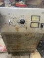
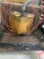
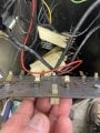
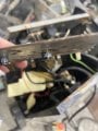
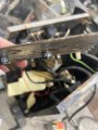
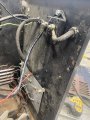
There are 8 button diodes, one for each of those lines.
 

LesJones

Joined Jan 8, 2017
4,511
Re your question in post #20 Only you can answer that question as you can trace the wiring to the switch. If you draw out the wiring between the mains input and the transformer primary then we could tell you if the switch is controlling the primary of the transformer.

Les.
 

Tonyr1084

Joined Sep 24, 2015
9,744
One thing that needs to be considdered is that the selector switch MAY select taappings on the primary to make adjustments to the secondary voltages.
That thought had crossed my mind as well.
When measuring these wires, do they need to be unplugged from the button diodes?
Yes. They need to be completely disconnected from everything. As for the selector switch, like LessJones said:
Only you can answer that question as you can trace the wiring to the switch. If you draw out the wiring between the mains input and the transformer primary then we could tell you if the switch is controlling the primary of the transformer.
There has been far too little information provided for us to really do anything.

I'll lean back on my post where I suggested two possible battery chargers available at Harbor Freight - assuming you have such in your area. I'm sure they're not everywhere. Nevertheless, those links could lead you to find something in your area.

And yes, I'm growing really concerned for your safety. I've said it many times - BE CAREFUL. VERY CAREFUL. But I'm starting to think this job might be beyond your reasonable ability to do it safely. The questions your asking suggests far too little understanding of how electronics (and electricity) works. I'm sure you are confident but I'm not as confident in you as you are. I'm not trying to be an azz hole here, not trying to cast dispersions on you or your ability but there are just too many possible accidental injuries that can occur - even to people who are consummate experts get hurt. Like I said before - I have been bitten a good number of times. Once I was lucky. Once I was DAMNED lucky. Most of the time I was just foolish and overconfident. Please don't hurt yourself following anyone's instructions if you're truly unsure of what you're doing. If you're a US Citizen we want you to have a good Thanks Giving tomorrow. Don't spend it injured. Or worse.
 
Last edited:

MisterBill2

Joined Jan 23, 2018
27,504
For the 12 volt charging I see three different voltages, 12.3 (2A), 12.8 (10A) and 14 (40A) plus the six volts 6.8v(40A)

Now I am thinking that it would have been better to have just cleaned it up, and then powered it up, and measured the output voltage for each switch setting with a fair load, such as a few back-up light bulbs, to present a load that would draw a few amps so that the actual voltage could be measured correctly. Often in a battery charger or jumper cables,, the failure is in the wire connection in the clamps.
I should have thought about that sooner, it seems.
One more thing is that most of the wires in the pictures do not look like 40 amp wires.
 
Last edited:

Thread Starter

stryped

Joined Sep 17, 2023
136
I took the metal plate off. The diodes say w 9049. It looks like some are orientated differently than others. It also looked like under the transformer 4 of the wires are grouped together on one side and 4 on the other. Could one side go to one terminal on the bridge rectifier and the other group go to the other? Attached are some more pictures. I will check voltages tomorrow.
 

Attachments

MisterBill2

Joined Jan 23, 2018
27,504
The view of the transformer is very interesting indeed. It might actually be that there are eight identical windings, each with one end connected to that black cable in the middle. Or maybe not.
Somebody skilled at understanding transformers could look at it and quickly know a whole lot in just a minute. Most others will be totally confused. At this point it would be very handy to see the actual circuit. Is a copy of it glued to an inside of a cover someplace??
I looked closely at the label, and it appears that the brand of charger is SCHUMACHER, or SCHUMAKER, or something like that. I think that company is still around. They would be able to provide some information. Probably a closer examination can reveal both the correct spelling and the city, which I guess is Chicago.
 
Last edited:

Thread Starter

stryped

Joined Sep 17, 2023
136
The view of the transformer is very interesting indeed. It might actually be that there are eight identical windings, each with one end connected to that black cable in the middle. Or maybe not.
Somebody skilled at understanding transformers could look at it and quickly know a whole lot in just a minute. Most others will be totally confused. At this point it would be very handy to see the actual circuit. Is a copy of it glued to an inside of a cover someplace??
I looked closely at the label, and it appears that the brand of charger is SCHUMACHER, or SCHUMAKER, or something like that. I think that company is still around. They would be able to provide some information. Probably a closer examination can reveal both the correct spelling and the city, which I guess is Chicago.
There is no circuit print out inside. Also no luck with the manufacturer…
 

MisterBill2

Joined Jan 23, 2018
27,504
OK, then it is time to: first, investigate the transformer primary arrangement, which may have taps selected for the slightly different output voltages, AND THEN, measure the voltages between those eight varnish insulated solid copper wires that go to the rectifiers. While they may all be 13 volts relative to the black common wire, I am guessing that there are opposite phases on half of them, so that there are effectively four center-tapped 24 volt windings. That will allow a bridge arrangement to provide 24 volts out, or 12 volts relative to the center tap connection.
Probably the six volts is provided by one more primary connection to reduce all of the secondary voltages. That is what I have seen on most of the six volt/twelve volt chargers I have repaired.
So there may be the ability to create a six. twelve, and 24 volt charger.
 

Tonyr1084

Joined Sep 24, 2015
9,744
Screenshot 2024-11-28 at 9.39.44 AM.png
The incoming cable from the left is apparently the main power cord. There's a HOT wire (black), a Neutral Wire (white) and a Ground Wire (green). The first place it is going is to the timer control (Timer). Next to that is the missing selector switch (Missing In Action). There's a heavy but split cable running through a clamp like thing (I don't know what that is) but it's connected to the amp meter (Ammeter). One thing I didn't identify was the switch to the left of the Ammeter, the selector switch that chooses between 6V and 12V.

It appears the white wire is tied to a red and a black wire, where they go is beyond the scope of this picture. Having seen the face of this battery charger it's a lot like one I have in my garage. Similar but not the same. And no, I'm not going to open it up just to take a look at how it's wired internally.

The transformer is a thorough mystery to me. I've seen multi-tapped transformers plenty of times but never one like that. So I really can't speak to its construction. At this point, if this were MY project, I'd be opting for something new. I know, I know, I keep harping on new. The reason for me is the age and condition of this machine. If this were an antique I could see saving it. But it's not an antique. And I see no value in repairing such an old beast. Especially when what's on the market now is far superior to this old dinosaur of a charger.

I understand you wish to rebuild it. That's perfectly fine. As long as you understand you may get mixed results. And if put back together incorrectly you could cause further problems. This is where a schematic, the language of electronics, is the best approach. Photographs may help in getting it back together the way it was but I'm just really suspect of the possibility of success on this endeavor. I wish you well. And a happy Thanks Giving (if you celebrate it).
 

Thread Starter

stryped

Joined Sep 17, 2023
136
That red wire taped to the white and black wire is a temporary connection. Both those wires went to the switch.
I have done some checking, it looks like one set of 4 wires are o volts. The other set of wires all have the same voltage. That voltage changes depending on which wire is engaged at the switch. One reason for repairing is it was my dad’s and I grew up with it. The other is they are 140 bucks and up. I attached a picture of some of the voltages if you can see it. Thanks very much for your help
 

Attachments

Tonyr1084

Joined Sep 24, 2015
9,744
What is this wire?
Screenshot 2024-11-28 at 11.12.34 AM.png
Is there more to this spreadsheet? It looks incomplete. Incomplete information results in an inaccurate answer.
Screenshot 2024-11-28 at 11.18.06 AM.png
Looking at this sheet it looks like zero ohms (relatively speaking) between wires 1, 2, 3 & 4. Suggests there's some sort of internal connection. On wires 1 & 5 you show 21.5V and 0Ω. But the numbers change when you connect to different color wires. I don't know what those wires are or where they go. Give me a few min's and I'll bang out a drawing of a multi-tapped transformer, one that MIGHT be similar to what you have.
 

Tonyr1084

Joined Sep 24, 2015
9,744
Screenshot 2024-11-28 at 11.28.13 AM.png
The left transformer has four wires on (typically the left side) the Primary windings. In both drawings the primary is drawn the same. This is not to suggest any particular ratio, just the basic understanding of a transformer. Also on the left drawing there is a multi-tapped secondary (typically the right side of the transformer drawing). This side is most commonly a lower voltage and a higher amperage.

The right transformer has the same primary configuration (for no other reason than ease of drawing) but the secondary side has three isolated secondary windings. These windings can be configured in different ways. You can series the top and the middle winding for a higher voltage (just because I happened to draw it this way) or you can parallel (for instance) the top and bottom secondaries for for higher amperages. IF the center secondary were the same size then you could parallel all three secondaries for an even higher amperage - AS LONG AS THE VOLTAGE OUTPUTS ARE THE SAME!

In either drawing, it's common to see a primary with a single center tap and a transformer wired (designed) for 110 or 220 VAC. In the case of 110VAC you'd use only one half of the primary (If I didn't get that mixed around). In the case of 220 VAC you'd use the two outer most leads and ignore the center tap. In the case of a multi-tapped primary you could literally select numerous options for voltage outputs. Since the transformer in question is associated with a 6V or 12V selector switch it's possible the switch is selecting between the two outer leads (for 12V) or just one of the two outer leads and the center tap (for 6V). Keep in mind I'm poor on transformers and I may have some of my statements reversed. If so - someone who is far better associated with transformers will correct me.

Somewhere I have a drawing of a multi-tapped transformer in my files. When I find it I'll post it along with voltages associated with each set of secondaries as well as a center tapped primary for operation on a 110 VAC system or a 220 VAC system. If I can find it I'll post it - just for informational sakes and hopefully to enlighten you on how they function.

[edit] it must be on another computer. [end edit]
 
Last edited:

Thread Starter

stryped

Joined Sep 17, 2023
136
Another thing I noticed is the position of the diode alternate plug one it’s upside down plug two right side up three upside down for right side up five right side up six upside down seven right side up eight upside down. I’m trying to understand how that affects the voltage but I assume it does. These are round diode, but I can’t tell Cathode marking they are soldered to the metal plate on one side and have a spade tab soldered on the other
 

Attachments

Thread Starter

stryped

Joined Sep 17, 2023
136
Tha
What is this wire?
View attachment 336877
Is there more to this spreadsheet? It looks incomplete. Incomplete information results in an inaccurate answer.
View attachment 336878
Looking at this sheet it looks like zero ohms (relatively speaking) between wires 1, 2, 3 & 4. Suggests there's some sort of internal connection. On wires 1 & 5 you show 21.5V and 0Ω. But the numbers change when you connect to different color wires. I don't know what those wires are or where they go. Give me a few min's and I'll bang out a drawing of a multi-tapped transformer, one that MIGHT be similar to what you have.
That black wire is negative to ground
 

Tonyr1084

Joined Sep 24, 2015
9,744
Another thing I noticed is the position of the diode alternate plug one it’s upside down plug two right side up
First, it doesn't matter which orientation of the spade lug (the tab) is facing. Diodes conduct current in one direction and block it in the opposite.
That black wire is negative to ground
Negative to ground. Are we referring to the same thing? Unfortunately your photographs are not complete enough to tell for sure what is what or where goes what. I believe you referred to the diode plate (insulated by plastic standoffs) as a ground. This is just a guess, but the negative lead is not going to be grounded to anything. The transformer isolates mains power from the charging circuit. So if you're saying that black wire coming from the transformer is the negative lead - then it's the negative lead.

What I THINK I'm seeing is half the wires from the secondary are bundled together forming the negative cable. The wire coming off the diode plate (possibly) is the positive cable. This is why it is so important to have a schematic. An ACCURATE schematic. Working off of photographs that don't show the whole thing in a single shot, which if you took one would probably lack detail, makes it difficult to figure out what goes where.

So I'll assume the following:
Screenshot 2024-11-28 at 12.45.56 PM.png
This drawing does not take into account, nor does it assume any kind of voltage or amperage switching.
 

Tonyr1084

Joined Sep 24, 2015
9,744
The following shows how the current is rectified.
Screenshot 2024-11-28 at 12.51.12 PM.png
You said you wanted Full Wave Bridge Rectification. That looks like this:
Screenshot 2024-11-28 at 12.54.36 PM.png
Judging by the size of the diodes on the diode plate, your Bridge rectifier is going to be a darned big one.

Let me ask you a question: Does (or did) the charger work before you started this project?
 

Attachments

Thread Starter

stryped

Joined Sep 17, 2023
136
The following shows how the current is rectified.
View attachment 336887
You said you wanted Full Wave Bridge Rectification. That looks like this:
View attachment 336889
Judging by the size of the diodes on the diode plate, your Bridge rectifier is going to be a darned big one.

Let me ask you a question: Does (or did) the charger work before you started this project?
It seemed like the voltage was low. My voltmeter said 8 volts when charging at 12 volts 2 amps. I was attempting to charge a four wheeler battery that never would charge, although it’s possible the battery was toast.
 

Thread Starter

stryped

Joined Sep 17, 2023
136
First, it doesn't matter which orientation of the spade lug (the tab) is facing. Diodes conduct current in one direction and block it in the opposite.

Negative to ground. Are we referring to the same thing? Unfortunately your photographs are not complete enough to tell for sure what is what or where goes what. I believe you referred to the diode plate (insulated by plastic standoffs) as a ground. This is just a guess, but the negative lead is not going to be grounded to anything. The transformer isolates mains power from the charging circuit. So if you're saying that black wire coming from the transformer is the negative lead - then it's the negative lead.

What I THINK I'm seeing is half the wires from the secondary are bundled together forming the negative cable. The wire coming off the diode plate (possibly) is the positive cable. This is why it is so important to have a schematic. An ACCURATE schematic. Working off of photographs that don't show the whole thing in a single shot, which if you took one would probably lack detail, makes it difficult to figure out what goes where.

So I'll assume the following:
View attachment 336885
This drawing does not take into account, nor does it assume any kind of voltage or amperage switching.
That black wire in the transformer goes to a box on the back of the cover. The negative charging cable also attaches to this box.
 

Attachments

Tonyr1084

Joined Sep 24, 2015
9,744
it’s possible the battery was toast.
This is why I always say "Fully diagnose the problem before beginning repairs." If you can - put it back together and get it on a known good battery and see if the charge is going up. Watch the voltage AND watch the amperage. A nearly fully charged battery will only draw a few amps. A weak battery will draw much more current. A bad battery may never draw any amps no matter what.

Put it back together if you can. Then test it. KNOW what you're doing before you start.
 
Top