Facebook
 Google
 GitHub
 Linkedin
Hi team,
I have discovered this is a somewhat complex task, I thought it would be easy. I have a bunch of Solar LED string lights (multiple sets), and all the batteries are now dead after a year or so of use. Rather than replace the batteries, I thought why not run them off a dc wall wart as I have a plug nearby.
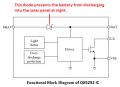
Using one set as my example, it has 30 bulbs in parallel, the current draw is 16mah which I believe I need to times by 30 equalling 0.48 mah. The battery is 1.2v 600mah, with an 8 pin unmarked chip doing voltage boosting, I am taking a somewhat educated guess the pulsing voltage is 3.0v but I can't say for sure.
I would really like to keep the features of the solar module - auto on/off and the different flashing modes. So my plan was to attach the DC mains supply to the battery terminals rather than to the led's.
I may be way off here, but what I have thought was to best replicate the battery was use a 5v, 1.2a wall wart, with a resistor in series and connect it to the battery terminal, I am aware the led's will take all the current that's on offer to them so to avoid burning anything out I have calculated like so:
30 x 0.016 = 0.48 mah
5v - 1.2v = 3.8v drop
3.8 / 0.48 = 8 ohm resistor
3.8 x 0.48 = 1.8 watt resistor
and the closest the shops sells: 8.2 Ohm 5 Watt Wire Wound Resistor
I am sure there is a better (maybe more energy efficient) way of doing this, so open to any suggestions. I Also need to stop the solar panel sending charging current back down the dc supply during the day, I thought either a diode or trial and error with unsoldering pins.
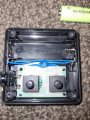
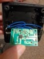
For reference the circuit board pics are attached.
I have discovered this is a somewhat complex task, I thought it would be easy. I have a bunch of Solar LED string lights (multiple sets), and all the batteries are now dead after a year or so of use. Rather than replace the batteries, I thought why not run them off a dc wall wart as I have a plug nearby.
Using one set as my example, it has 30 bulbs in parallel, the current draw is 16mah which I believe I need to times by 30 equalling 0.48 mah. The battery is 1.2v 600mah, with an 8 pin unmarked chip doing voltage boosting, I am taking a somewhat educated guess the pulsing voltage is 3.0v but I can't say for sure.
I would really like to keep the features of the solar module - auto on/off and the different flashing modes. So my plan was to attach the DC mains supply to the battery terminals rather than to the led's.
I may be way off here, but what I have thought was to best replicate the battery was use a 5v, 1.2a wall wart, with a resistor in series and connect it to the battery terminal, I am aware the led's will take all the current that's on offer to them so to avoid burning anything out I have calculated like so:
30 x 0.016 = 0.48 mah
5v - 1.2v = 3.8v drop
3.8 / 0.48 = 8 ohm resistor
3.8 x 0.48 = 1.8 watt resistor
and the closest the shops sells: 8.2 Ohm 5 Watt Wire Wound Resistor
I am sure there is a better (maybe more energy efficient) way of doing this, so open to any suggestions. I Also need to stop the solar panel sending charging current back down the dc supply during the day, I thought either a diode or trial and error with unsoldering pins.
For reference the circuit board pics are attached.
Attachments
-
 1.9 MB Views: 43
 -
 1.3 MB Views: 40