Controlling parallel LEDs with potentiometer problem.

Thread Starter

ThisNameHasNotBeenUsed

Joined Nov 4, 2022
14
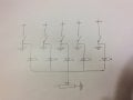
I am using multiple LEDs (20mA 3-12V) in parallel to indicate active circuits in a car. They are too bright at night, so I put a 250K potentiometer to their collective ground. At less resistance, some LEDs are brighter than others. At greater resistance, the brightest LEDs become the dimmest. 1. How do I make them respond equally? 2. Will they eventually burn out when set at least resistance at the pot? 3. Why is this happening?
 

WBahn

Joined Mar 31, 2012
29,978
You really need to provide a schematic of what you have. A potentiometer is a three-terminal device. How do you have it hooked up?

What do you mean by "(20mA 3-12V)"? Again, a decent schematic would make this clearer.

The basic approach you are taking has a number of issues, but we need to see the actual schematic to go much further.

Why 250 kΩ? If you put the entire 12 V across the 250 kΩ you would have less than 50 µA, so all of your sensitivity is going to be at one end of the pot's wiper travel.
 

dl324

Joined Mar 30, 2015
16,845
Welcome to AAC!

It would be helpful if you drew a diagram showing how you have the LEDs connected, so we can see why some might be brighter than others.

Are these all "automotive" LEDs (i.e. the type that have built-in resistors to operate from 12V)? Or they really spec'ed to operate from 3-12V.

FWIW, using a pot to dim LEDs is usually not the way to go. The right way to do it is to use PWM so you can get a more linear dimming response, but that's probably more complicated than you want to deal with. In any case, a 250kΩ pot is too large.
 

LowQCab

Joined Nov 6, 2012
4,023
LEDs need some sort of a Current-Regulator,
a Resistor is the most crude form of a Current-Regulator,
but when used correctly, they will work just fine on a LED.

But now You want to complicate things with differently-Rated LEDs.

In order to not have any surprises from miscommunications,
a Schematic-Diagram showing exactly what You are doing is required.

After the Current-Limiting for each LED has been sorted-out,
then we can talk about a simple PWM-Dimmer, controlled by a Pot.
.
.
.
 

WBahn

Joined Mar 31, 2012
29,978
Can you provide a part number or a link to the LEDs you are using? It will help us all stay on the same page.
 

Thread Starter

ThisNameHasNotBeenUsed

Joined Nov 4, 2022
14
What is the easiest way to make a schematic for here? The pot is wired center and tapered side of an audio taper. I had the pot handy so that’s why I used it. The LEDs are from eBay: “Chanzon 8MM indicator light kit BA0023x10 8MM mounting hole”. That’s all the package says. There is no indication that the LEDs are automotive, but it does say 3-12V. I don’t see any resistors. Could they be too small to see? I didn’t think this would become complicated.
 

dl324

Joined Mar 30, 2015
16,845
What is the easiest way to make a schematic for here?
It doesn't have to be anything fancy. Hand drawn diagrams are fine.
There is no indication that the LEDs are automotive, but it does say 3-12V.
For your application, they don't need to be. But when you talk about things operating from 12V, we're going to assume that they're designed for automotive applications.

The good ones will have current sources built in so brightness won't vary with supply voltage.
I didn’t think this would become complicated.
It isn't if you know what you're doing.
 

dl324

Joined Mar 30, 2015
16,845
Is this okay?
It's okay, but that isn't really what you have. As shown, the LEDs would never turn on.

The problem is that you have multiple LEDs in parallel and LEDs from Ebay aren't going to have matched forward voltages. That's what's causing most of your problems.

Are all of the LEDs the same color?
 

dl324

Joined Mar 30, 2015
16,845
This is what I have to go by.
That's pretty typical of many things from Ebay. The sellers are just selling things, often have little technical knowledge, and the descriptions are vague and/or incorrect.

LEDs of different colors have different forward voltages. White and blue will be in the 3-5V range. The rest are going to be closer to 2-3V. To operate at 12V, they'll need something to limit current (resistor, current source, or PWM). LEDs of the same color from the same batch can be matched for brightness or forward voltage. Matching by brightness is the most common, but you only get matched brightness if you operate them at the same current.
 

Thread Starter

ThisNameHasNotBeenUsed

Joined Nov 4, 2022
14
I am using white, blue, red and yellow. Their sensitivity runs in the same order, from highest to lowest. I am also using green, but I haven’t tested that one yet.
 

dl324

Joined Mar 30, 2015
16,845
I used the middle and (I believe) the left. Sorry about the goof on the pot symbol. Thanks for your patience.
The goof is showing the LED anodes connected to ground. When you close the switches, you would be shorting the supply voltage to ground and something is going to give. Also, where you have the pot connected to the LED anodes, you should draw a connection dot.
1667621178169.png

The bottom line is that you have 5 LEDs of different colors connected in parallel and that isn't going to give you uniform brightness.
 

LowQCab

Joined Nov 6, 2012
4,023
This is the type of PWM-Circuit that You need ................
Do You need help with exact Part-Numbers ?
You may be able to buy a similar Controller from China ready to use.
.
.
.
Alternative Dimming Circuit Flat .png
 

Thread Starter

ThisNameHasNotBeenUsed

Joined Nov 4, 2022
14
The goof is showing the LED anodes connected to ground. When you close the switches, you would be shorting the supply voltage to ground and something is going to give. Also, where you have the pot connected to the LED anodes, you should draw a connection dot.
View attachment 279966

The bottom line is that you have 5 LEDs of different colors connected in parallel and that isn't going to give you uniform brightness.
Thanks for the tip. Sorry. The ground symbols were a shortcut. They all actually go to various circuits in the car. e.g. Accessory 1, accessory 2, ignition, radio/data interface, and headlights/night light circuit.
 

xox

Joined Sep 8, 2017
838
Why not put pots on all of them? Adjust accordingly, then the differences when operating the "master" potentiometer will likely be minimal.
 
Top