controlling buttons with one pin

Thread Starter

Zulkifal

Joined Feb 5, 2016
18
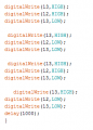
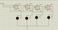
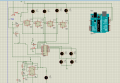
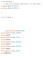
In my project I want to control multiple buttons with only one to two pins of microcontroller so I made shift register with D-flipflops when I give the desired signal like 1011 it shifts and after a while clock signal is continuous so my values didn't match to the desired value so I put Latch to store the values and put a transistor to stop clock pulse so my values gets stored in the latch the pulse which i give from Proteus is 2 Hz and in Arduino code I put delay so my desired logic worked .
but in real time I am giving it pulse from timer and it is very fast I changed the delay it worked for a second but after sometimes it fails how will I able to do this and in real time If somehow clock signal is generated correctly how will I be able to do this ..
 

Attachments

AlbertHall

Joined Jun 4, 2014
12,625
L10 to L18 are labelled as 12V. The arduino is producing 5V signals. What voltage are the logic chips in your circuit using as their power supply?
 

Thread Starter

Zulkifal

Joined Feb 5, 2016
18
I don't want to turn the led on with the 5v signal It was just to let me know my bits are shifted sorry for that.

my logic works for signal signal for 2 Hz but it was too slow i try to make it fast but my calculations happens to be wrong what should I do to make it work In this way I am using 2 pins of Arduino serial in parallel out for shift register.
 
Last edited by a moderator:

AlbertHall

Joined Jun 4, 2014
12,625
From the uno, you can set the D input to the shift register as desired and then pulse the clock. Do this four times and the shift register now holds the desired value. You can do this pretty quickly so if the outputs are driving LEDs it will be much too fast for your eye to see so you will just see the LEDs take up the new values.

Incidentally, the code which you show pulses pin 13 (presumably the clock) only twice and the setting for pin 12 (presumably the D input) doesn't change during this sequence.

What are the '555 and the '273 supposed to add to this circuit?
 

Thread Starter

Zulkifal

Joined Feb 5, 2016
18
So if I connect the relay to this parallel out would it be very fast triggering for the relay .I want the triggering to happen so i used the latch to hold the values .
first I give the pulse from Proteus then i Made clock pulse from 555.
 

AlbertHall

Joined Jun 4, 2014
12,625
The changes can be much faster (a few microseconds) than a relay could respond to, so again all that will happen in reality is that the relays would take up the new settings.
 

Thread Starter

Zulkifal

Joined Feb 5, 2016
18
Pin 13 is for the data.
pin 12 is connected to the transistor so that it disables the clock and let the latch to hold the value.
Clock is not given through pin 13 it is connected externally.

I wasn't aware of this i will try thanks for your reply

Another thing I want to ask if I give pulse signal from arduino
like I make a loop how rest program will execute.
 
Last edited by a moderator:

AlbertHall

Joined Jun 4, 2014
12,625
The clock pulse width for the 74HC74 could be 24nS at 5V supply. I think that is faster than the uno can produce. Let's say the uno can manage 1uS wide pulses then the loop to output the four bits would take about 12uS. During this time the uno cannot do anything else. The update of the outputs for relays or LEDs would not need to be more often than, say, 20mS so only a small proportion of the uno's time will be spent doing this output.
 

Thread Starter

Zulkifal

Joined Feb 5, 2016
18
Iam confused if i put loop like this in arduino
While(1){

And in it I put pin 13 to delay microsecond
To produce pulse if clock is in infit loop how furture program will execute


}
 

AlbertHall

Joined Jun 4, 2014
12,625
You put everything else that it has to do inside that loop as well - for instance.
Better, your other code calls the routine that sends the four bits whenever the code is to be changed.
 
Top