Controlling an RF spdt using two opposite p-channel mosfets and a logic pin

Thread Starter

breakarn

Joined Sep 25, 2020
4
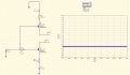
Hi, I am trying to control an RF SPDT switch which has two control voltage pins V1 and V2. The truth table for the SPDT is attached. Now what I want to achieve is controlling the opposite voltages (0v and -5V) using two p-channel mosfets to deliver these voltages. The gate of the mosfets will be connected to an output pin of a microcontroller which has a voltage of 5V at logic level 1. I was able to set up such a circuit in a simulator however only with positive voltages. Once I make it -5V it all becomes a bit counter-intuitive for me.

If i set the voltage sources to -5V then the mosfets never turn off obiously, no matter what i set my logic to because:
Logic0 (0V gate): 0-(-5) = 5V= Vgs
Logic1 (5V gate): 5-(-5) = 10V Vgs

How would I tackle this issue? any help in the right direction is very helpful. thank you

edit: i have looked all over the internet for controlling mosfets with a negative supply I cannot find anything. But maybe i am googling the wrong words.
 

Attachments

LowQCab

Joined Nov 6, 2012
4,072
You neglected to mention the overall problem that you are trying to solve.
Are you talking about a "Radio-Frequency" "Single Pole Double Throw" switch ?
What is that ???
Are you working on an Antenna Switch ?
If you are playing with RF, there are a whole bucket-full of different rules and black magic that come into play.
What are you working on ?
What is the end result you trying to accomplish ?
 

Thread Starter

breakarn

Joined Sep 25, 2020
4
You neglected to mention the overall problem that you are trying to solve.
Are you talking about a "Radio-Frequency" "Single Pole Double Throw" switch ?
What is that ???
Are you working on an Antenna Switch ?
If you are playing with RF, there are a whole bucket-full of different rules and black magic that come into play.
What are you working on ?
What is the end result you trying to accomplish ?
Thank you for your reply. Sorry I should have been more clear. I am very clear on the RF aspect of my switch, its just that I havent dealt with mosfets in years. Here is more detailed explanation:

I am trying to control a very high frequency RF SPDT switch, datasheet linked here:
https://cdn.macom.com/datasheets/MASW-008322.pdf

With the two control voltage V1 and V2 I am able to select which output is on RF1 or RF2
The truth table for the SPDT (on page 2) is always opposite inputs on V1 and V2. If you want RF1 on and RF2 off then V1=LOW and V2=HIGH and vice versa. Now in this SPDT case the LOW = -5V and HIGH=0V.

What I am trying to achieve is having a microcontroller connecting one pin to an inverter. Logic HIGH from the microcontroller is +5V. One mosfet gate will be connected BEFORE the inverter and one mosfet will be connected AFTER the inverter.
Hence e.g: when microcontroller is outputting Logic 1: one mosfet will be open and one mosfet willbe closed and vice versa when outputting LOW from microcontroller.

My issue is: how do i set this up with the mosfets? Again, I havent played with mosfets in many many years and on the internet i am only finding situations where the supply voltages (source) is positive and not negative.
 

sghioto

Joined Dec 31, 2017
5,390
Do you have to use that switch? There are other medium power RF switches that will work with positive voltages. Then you can control it with just the micro.
SG
 

AlbertHall

Joined Jun 4, 2014
12,346
The P MOSFETs would need to have their sources connected to 0V so they could pull V1 and V2 up to 0V but that means that their gates need to be pulled down to -5 to turn them on which the inverter can't do.

The PNP in my suggested circuit is not an inverter but instead is used as a level converter so 0V to 5V becomes -5V to 0V.
 
Top