 Facebook
 Google
 GitHub
 Linkedin
Hi all,
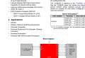
I'm controlling a trigger system through fiber links. The optical transceiver for triggering the pulse that activate the channel is commanded by a port expander which I send commands through I2C to write it registers. The problem is that once I connect the system and I feed the board where the port expander and the transceiver are, the indeterminate states of the IO pins of the port expander gives 1.6V till I write the registers with 0, this 1.6V are enough for activate the LED of the transmitter, having a logical high state in the other side, although the system is 0V-5V. I don't want to write specifically 0 in the registers to have 0V at the output, and a pull down resistor makes no sense because I have 1.6V at the output of the port expander. How could I do to assure that I have 0 at the IO outputs although the board is feeded and still I don't wrote the registers for have 0 at the output ?
https://www.ti.com/lit/ds/symlink/tca9535.pdf?ts=1635761395944&ref_url=https%3A%2F%2Fwww.google.com%2F
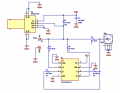
In the other hand at the receiver where I use this scheme:

I get RXVCC (5V) in RXD when there is no light in the fiber, and 0.325V when there is light. I want to get the opposite, 0V or 0.325V (low state) when there is no light and 5V when there is light in the fiber.
I based my design on that:
https://docs.broadcom.com/doc/AV02-2656EN
https://docs.broadcom.com/doc/AV02-0176EN
Thanks in advance
Jesus
EDIT: Sorry about the subject, I made a mistake in the title and now I can't edit that.
I'm controlling a trigger system through fiber links. The optical transceiver for triggering the pulse that activate the channel is commanded by a port expander which I send commands through I2C to write it registers. The problem is that once I connect the system and I feed the board where the port expander and the transceiver are, the indeterminate states of the IO pins of the port expander gives 1.6V till I write the registers with 0, this 1.6V are enough for activate the LED of the transmitter, having a logical high state in the other side, although the system is 0V-5V. I don't want to write specifically 0 in the registers to have 0V at the output, and a pull down resistor makes no sense because I have 1.6V at the output of the port expander. How could I do to assure that I have 0 at the IO outputs although the board is feeded and still I don't wrote the registers for have 0 at the output ?
https://www.ti.com/lit/ds/symlink/tca9535.pdf?ts=1635761395944&ref_url=https%3A%2F%2Fwww.google.com%2F
In the other hand at the receiver where I use this scheme:
I get RXVCC (5V) in RXD when there is no light in the fiber, and 0.325V when there is light. I want to get the opposite, 0V or 0.325V (low state) when there is no light and 5V when there is light in the fiber.
I based my design on that:
https://docs.broadcom.com/doc/AV02-2656EN
https://docs.broadcom.com/doc/AV02-0176EN
Thanks in advance
Jesus
EDIT: Sorry about the subject, I made a mistake in the title and now I can't edit that.
Attachments
-
 130.8 KB Views: 0
 -
 138.2 KB Views: 0
Last edited:


