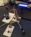
Control Dyson DC35 Multifloor vacuum cleaner motor

Thread Starter

Frank Bolleri

Joined Sep 23, 2023
77
You understand correctly. So Dyson would likely drive the motor with an increasing voltage (achieved using PWM) and Hall-triggered increasing frequency as the speed ramps up, as shown in post #66.
I'm convinced you're right, but I need to elaborate on your observation a bit, I'll think about it.

The point is that I don't understand, seeing how it is built, why it shouldn't work simply by controlling the frequency without the introduction of the hall sensor.
Before doing anything else, I would like to try supplying more current (not too much, maybe reach 10A) with the current configuration, and see if the possible frequency goes up.

But first I have to find another power supply, unless I put two in parallel...

About this latest point: reading around I find conflicting opinions on putting power supplies in parallel to increase the current - it seems to me that there are those who say "absolutely not!" and those who say "you definitely can!".
Then there are those who say that you have to be careful, but that you can do it and who seem to me to be the most credible.

For example:

This one tell that you need to put one in Constant Voltage mode and others in Constant Current mode
https://edadocs.software.keysight.c...ble of CV/CC,of the individual power supplies.

These others tells about resistors in between:
https://electronics.stackexchange.c...ow-to-design-a-parallel-able-lab-power-supply
https://www.accelinstruments.com/Applications/TS200/Waveform-Amplifier.html (chapter More Output Current)

Here talks about diodes... but seems to me that does not suggest to try
https://www.eevblog.com/forum/beginners/hooking-up-two-24-vdc-power-supplies-in-parallel/

I am also thinking to get some old PC power supply able at least to provide 10A.
 

MisterBill2

Joined Jan 23, 2018
19,613
I think you didn't understand why I mentioned the hall sensor.
It was referring to the motor control process, not as an alternative method to reading the voltage across the coil.
Thanks for the suggestion about the capacitor value: I will take it into consideration after evaluating any other answers.


What a shot! I'm so happy that you consider me an engineer!
Quite a step forward, considering you didn't even think I'd be able to get the engine running.
But unfortunately I'm not an engineer... I'm just a curious person, who tries to spend the limited free time he has having fun and learning something, with the humility to ask when he doesn't know or understand something and who always thanks when someone helps him.
It says"Engineer" in the information area about the poster. So there is where I saw the statement about "being an engineer."
Understanding what a participant already knows is useful in responding with an adequate explanation.
 

Alec_t

Joined Sep 17, 2013
14,430
The point is that I don't understand, seeing how it is built, why it shouldn't work simply by controlling the frequency without the introduction of the hall sensor.
You have proved that it 'works', in the sense that you can get the motor to rotate, but it won't be working optimally. If the flux reversal isn't synchronised with the actual rotation then at some instants the torque due to the flux will be opposing the rotation instead of aiding it..
 

MisterBill2

Joined Jan 23, 2018
19,613
Is there any intent towards returning this device to being a useful vacuum cleaner?? Or any other purpose? Or is this just experimenting?
 

Thread Starter

Frank Bolleri

Joined Sep 23, 2023
77
It says"Engineer" in the information area about the poster. So there is where I saw the statement about "being an engineer."
Understanding what a participant already knows is useful in responding with an adequate explanation.
When subscribed, I have choosed Computer Engineer because seems to me more affine to what I do in my daily occupation, but I have not any degree: I have cleared that value.
However, this does not mean that if I ask for connection instructions you are entitled to make annoying considerations.
If I ask it's because I don't know.
 

Thread Starter

Frank Bolleri

Joined Sep 23, 2023
77
You have proved that it 'works', in the sense that you can get the motor to rotate, but it won't be working optimally. If the flux reversal isn't synchronised with the actual rotation then at some instants the torque due to the flux will be opposing the rotation instead of aiding it..
Ok, thank you.
 

Thread Starter

Frank Bolleri

Joined Sep 23, 2023
77
Hello all,
I thought a bit about @Alec_t 's suggestions, then I equipped myself and now... beyond any initial expectations!
Screenshot 2023-11-10 at 01.11.10.png
Magnetic feedback works great!


Below, the steps followed.

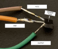
For first, I have detached the original hall sensor.
Unfortunately, it was damaged during desoldering (it lose "out" leg), but with an acrobatic welding I was able to recover it.
Screenshot 2023-11-10 at 00.53.51.png
So, I have learned something about hall sensors... and with some empirical test I have discovered that this is not linear, bipolar: each change of magnetic pole exposition on the sensor face will trigger the digital output state change.

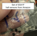
So, I have purchased this cheap package of bipolar hall sensors:
Screenshot 2023-11-10 at 00.59.17.png

Then, using the little original black piece of plastic, I have mounted the sensor and relative wiring.
Screenshot 2023-11-10 at 01.01.11.png

Test of the sensibility of the sensor mounted:
Screenshot 2023-11-10 at 01.02.04.png

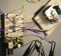
Then I have substituted signal generator input in my circuit, so now the input of the NOT logic port IC is directly from the hall sensor:
Screenshot 2023-11-10 at 01.03.41.png

And this is the final appearance before the test on the video.
Screenshot 2023-11-10 at 01.04.11.png

I have also purchased a 30V 20A power supply (that's what you see in the video) but it probably wasn't really necessary.
In the test of the video I have used just 3.3A and it already looks like an airplane...
Patience... I have a new and powerful instrument in the laboratory.
Screenshot 2023-11-10 at 01.06.50.png


Ah... last but not least:
A 1uF non-polarised cap in series with the scope probe negative should do the job.
This suggestion to isolate oscilloscope works perfectly.
I didn't actually have a 1uF unpolarized: I used a 700nF, but it worked anyway.
This was the image taken some days ago with motor running at 72 Hz, even if perhaps now the need is outdated.

Screenshot 2023-11-10 at 00.45.18.png

Is there any intent towards returning this device to being a useful vacuum cleaner?? Or any other purpose? Or is this just experimenting?
I wanted to experiment, but maybe now I'll put it back in the vacuum cleaner!
:p
Thanks to everyone who contributed and a special thanks to @Alec_t!
 
Last edited:

Thread Starter

Frank Bolleri

Joined Sep 23, 2023
77
Hello all,
just to close this "project", a little and final update.

After the succesfull run based on hall sensor feedback, I continued to study and develop the solution.

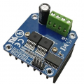
For first, I have changed the h-bridge module, moving to BTS7960 43A in order to be able to work at 22.2 V like the original Dyson battery.

Screenshot 2023-12-18 at 00.24.44.png

Then, I have explored the possibility to use PWM to control the speed of the motor, passing through a solution based on the SN74LS138N demultiplexer on which I entered with the PWM signal coming from the function generator and, alternatively routing (based on the feedback of the hall sensor) the PWM signal on the two inputs of the H Bridge.

Screenshot 2023-12-18 at 00.42.35.png

Even though this is also a very simple circuit, It worked very well; but at this point the dependency on the function generator was annoying.

For this reason, in the next step I decided to check if I could use an ESP32 microcontroller to generate the necessary PWM signal, controlling it with a rotary encoder and interfacing it with the h-bridge.
Not only did I succeed very well, but I was also able to enrich the tool measuring the frequency (and therefore also the motor RPM) just adding the measure routine after the reading of hall sensor feedback necessary to invert the PWM channels; it was also easy to add an LCD display to show what happen internally.

To power the ESP32 with 5V I have used a 7805, attached directly to the main power supply of the h-bridge.

Screenshot 2023-12-18 at 00.47.12.png

When all works as expected, I have moved all the components into a prototyping PCB board
and designed also a separated little connection board in order to have a "plugin" approach for connecting the h-bridge:

Screenshot 2023-12-18 at 00.52.16.png

I have also re-installed the motor inside the original enclosure, creating a little PCB to mantain the hall sensor stably in place.
In the pre-existent hole in the enclosure I have installed an "aviation plug" with 5 pins (2 for motor and 3 for hall sensor).

Screenshot 2023-12-18 at 01.02.34.png

Then I have installed all inside a cheaper electrical box:

Screenshot 2023-12-18 at 01.07.21.png

And finally... If I want to run my Dyson with a wired power chord (which was the original purpose, before the original driver was burned) I just have to detach the battery powered motor unit (I have purchased another by second hand, very cheap) and attach mine:

Screenshot 2023-12-18 at 01.12.27.png


It was a great experience for me, very fun and instructive and I wanted to share the final result here.
I thank everyone for their attention and I wish you happy holidays!

Francesco
 

Alec_t

Joined Sep 17, 2013
14,430
Nice work, Francesco.
I watched an interview with James Dyson on TV last month, in which he briefly discussed his firm's 'digital motors'. Interestingly he stated that they can run at speeds up to 135000 rpm! I would be afraid of them disintegrating under huge centrifugal stress at that speed. That probably accounts for why the plastic casing was said to be made from the same material as body-armour!
Happy Christmas.
 

HasBeen

Joined Jul 28, 2023
30
Hello all,
just to close this "project", a little and final update.

After the succesfull run based on hall sensor feedback, I continued to study and develop the solution.

For first, I have changed the h-bridge module, moving to BTS7960 43A in order to be able to work at 22.2 V like the original Dyson battery.

View attachment 310202

Then, I have explored the possibility to use PWM to control the speed of the motor, passing through a solution based on the SN74LS138N demultiplexer on which I entered with the PWM signal coming from the function generator and, alternatively routing (based on the feedback of the hall sensor) the PWM signal on the two inputs of the H Bridge.

View attachment 310203

Even though this is also a very simple circuit, It worked very well; but at this point the dependency on the function generator was annoying.

For this reason, in the next step I decided to check if I could use an ESP32 microcontroller to generate the necessary PWM signal, controlling it with a rotary encoder and interfacing it with the h-bridge.
Not only did I succeed very well, but I was also able to enrich the tool measuring the frequency (and therefore also the motor RPM) just adding the measure routine after the reading of hall sensor feedback necessary to invert the PWM channels; it was also easy to add an LCD display to show what happen internally.

To power the ESP32 with 5V I have used a 7805, attached directly to the main power supply of the h-bridge.

View attachment 310204

When all works as expected, I have moved all the components into a prototyping PCB board
and designed also a separated little connection board in order to have a "plugin" approach for connecting the h-bridge:

View attachment 310206

I have also re-installed the motor inside the original enclosure, creating a little PCB to mantain the hall sensor stably in place.
In the pre-existent hole in the enclosure I have installed an "aviation plug" with 5 pins (2 for motor and 3 for hall sensor).

View attachment 310209

Then I have installed all inside a cheaper electrical box:

View attachment 310210

And finally... If I want to run my Dyson with a wired power chord (which was the original purpose, before the original driver was burned) I just have to detach the battery powered motor unit (I have purchased another by second hand, very cheap) and attach mine:

View attachment 310211


It was a great experience for me, very fun and instructive and I wanted to share the final result here.
I thank everyone for their attention and I wish you happy holidays!

Francesco
Excellent work!
 

Thread Starter

Frank Bolleri

Joined Sep 23, 2023
77
Nice work, Francesco.
I watched an interview with James Dyson on TV last month, in which he briefly discussed his firm's 'digital motors'. Interestingly he stated that they can run at speeds up to 135000 rpm! I would be afraid of them disintegrating under huge centrifugal stress at that speed. That probably accounts for why the plastic casing was said to be made from the same material as body-armour!
Happy Christmas.
Ciao!
In reality, at 22.2V (same as the original battery) I can obtain at maximum 66/67 kRPM (of course if the method I follow to read the frequency of hall switching is working correctly and if the formula RPM = Hz * 60 apply without "stranger things" to this motor... :) )

I buy DC35 more than ten years ago... probably the speed of recent models was improved since that date.
 

MaxHeadRoom

Joined Jul 18, 2013
28,853
Although most Universal vacuum motors can reach 22-24krpm, especially when blocked.
They are not particularly "expensive" motors.
In the case of BLDC, et-al, The rotor magnetic materials probably are capable of extreme centrifugal forces?
 
Hi @Frank Bolleri
Thanks for posting your research on DC 35 motor. And apologies to bring up this thread.

Your post inspired me a lot as my DC35 logic board is broken and I'm trying to ditch the board and add a control to the motor directly to save the vaccum.

So my plan:
Use an adjustable square wave generator (NE555), H-bridge and the original battery connection to revive the vaccum

From my experiments, I use:
6v 8.5A DC power (the voltage and amp can only be set priorly. Once set, they are not adjustable during the output)
IBT_2 as H bridge
an adjustable signal generator (I used flipper zero or NE555 based function generator)

Then I can only get the motor start to cycle at around 80-85Hz (and higher frequency requires high amps, which will also produce a high-pitched beep sound)

I'm very interested in the method that you mentioned using the hall sensor to feed the signal to the H-bridge, it seems that the hall sensor is connected directly to the H-bridge?

How does hall sensor work together with the PWM generator?

many thanks.
 

Thread Starter

Frank Bolleri

Joined Sep 23, 2023
77
Hi @Frank Bolleri
Thanks for posting your research on DC 35 motor. And apologies to bring up this thread.

Your post inspired me a lot as my DC35 logic board is broken and I'm trying to ditch the board and add a control to the motor directly to save the vaccum.

So my plan:
Use an adjustable square wave generator (NE555), H-bridge and the original battery connection to revive the vaccum

From my experiments, I use:
6v 8.5A DC power (the voltage and amp can only be set priorly. Once set, they are not adjustable during the output)
IBT_2 as H bridge
an adjustable signal generator (I used flipper zero or NE555 based function generator)

Then I can only get the motor start to cycle at around 80-85Hz (and higher frequency requires high amps, which will also produce a high-pitched beep sound)

I'm very interested in the method that you mentioned using the hall sensor to feed the signal to the H-bridge, it seems that the hall sensor is connected directly to the H-bridge?

How does hall sensor work together with the PWM generator?

many thanks.
Dear @dumbfingers I am really sorry to read your post only now. Excuse me for that.
Give me some time to prepare an appropriate answer to your question when I have some free time and I will be back to you soon.

Ciao!
Francesco
 
Dear @dumbfingers I am really sorry to read your post only now. Excuse me for that.
Give me some time to prepare an appropriate answer to your question when I have some free time and I will be back to you soon.

Ciao!
Francesco
Hi @Frank Bolleri

Thanks for your reply. Please take you time. I am also double checking my setup whilst waiting for some more components to arrive (inverter and demultiplexer)
So far I think I made a mistake on:
* not using an inverter

This explains why the motor would only run/turn at a higher frequency. Because without the inverter, the square waves will only have the positive halves.

I found that I may not phrased my question well and please allow me to rephrace my question:

What I would like to achieve:
use a 555 based function generator to generate square waves (and a potentiometer to adjust the frequency)
an IBT-2 as H-bridge, take input from the square wave, original battery as power source, to control the motor

So far I realised that I will need an inverter to be able to generate the square wave that provides both positive and negative halves.

May I ask:
what is the role of the hall sensor here? Is it acting as a feedback loop to tell the PWM to adjust its frequency?
 
Top