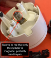
Control Dyson DC35 Multifloor vacuum cleaner motor

MaxHeadRoom

Joined Jul 18, 2013
28,853
Well aware, but in case where it was suspected to be shaded pole motor, they cannot achieve much over 3krpm, no where near enough for a vacuum cleaner application.
post #17
 

HasBeen

Joined Jul 28, 2023
30
Well aware, but in case where it was suspected to be shaded pole motor, they cannot achieve much over 3krpm, no where near enough for a vacuum cleaner application.
post #17
Agreed. I think in new designs they are trying to get the rpm up to where the sound from it is above the audible range (20KHz or so). There are still a bunch of other noise sources involved, like air movement, but the apparent mechanical noise is reduced.
 

Thread Starter

Frank Bolleri

Joined Sep 23, 2023
77
How many poles does the magnet have? (You may be able to tell from the 'cogging' felt as you rotate the shaft).
Hi!
The magnet on the shaft seems to me to have 2 poles.
If I understand.. the "cogging" is strong: if you rotate manually, it opposite a strong resistance to the rotation - but after some degree (seems to me apporaching 90°) "tac!": it turn of other 90° (and reach 180° with respect of the initial position)
So, the shaft have just 2 equilibrium positions.

I try (hope) to explain better with a drawing:
Screenshot 2023-10-24 at 23.57.48.pngScreenshot 2023-10-24 at 23.58.31.pngScreenshot 2023-10-24 at 23.58.55.png

And the same if you move it from 180°... you can pass from 90° or 270° to reach again 0°.

Some answers to some observation/questions readed from other posts:
  • following what I see in internet from other people, yes, i can confirm that this Dyson Motor is defined as a "bipolar switched reluctance motor"
  • there is not more elements of what I have documented with photos in post n°1: there are only 3 elements - and the shaft is not easily removable from the plastic body - and I do not want to break it
  • the stator is not/not contains magnetic element - the only magnet is on the shaft
  • but, as expected, if the stator coil (detached from the body motor) is powered with DC current, it became magnetic and can for example bring a screw - but no magnetism is detected without current flow.

I can add a photo of the stator mounted without a little plastic cover and more zoomed on the shaft, so it will be possible to observe the very thin distance between the magnet and the metallic part of the stator and the asymmetric shape of the metallic part.

Screenshot 2023-10-25 at 00.15.23.png

I think must exists some waveform at certain frequency that, with the right amount of current, can make it turn.
But I don't know what can be a correct approach for start - and I hope to have enough instrumentation... my dual power supply can provide MAX 3A. I have another power supply (single) that can provide MAX 5A.

This motor was mounted on DC35 Multifloor (I think is 200W power) original powered with a battery like that:
Screenshot 2023-10-25 at 00.24.40.png

I don't know If there is a possibility to activate the motor with "only" 3A or 5A...
Otherwise I have to purchase a more bigger power supply :)
 

MisterBill2

Joined Jan 23, 2018
19,613
If it has only two leads, how can it be a switched reluctance motor?? Evidently I missed that one in the electric motors class.
And while the picture is very good, it does not even show the whole motor. I do see two coils, so how can it be switched , with only two leads.
 

HasBeen

Joined Jul 28, 2023
30
If it has only two leads, how can it be a switched reluctance motor?? Evidently I missed that one in the electric motors class.
And while the picture is very good, it does not even show the whole motor. I do see two coils, so how can it be switched , with only two leads.
H Bridge?
 

MisterBill2

Joined Jan 23, 2018
19,613
OK, and a good point. Did any portion of that damaged PCB resemble an "H " bridge? I didn't see it. And how is the TS going to duplicate any form of it???
So while it can certainly be an "H" bridge driver, that is not the simplest scheme to implement. And for a vacuum cleaner it seems like the direction it spins will matter quite a bit, at least it did in all the ones I have studied.They are optimized for one direction of rotation..
 

shortbus

Joined Sep 30, 2009
10,049
The magnet on the shaft seems to me to have 2 poles.
How far is that magnet from the Hall sensor on the circuit board? I'm thinking that the magnet and Hall sensor tell the circuit board which electromagnet to turn on and when.

The actual rotor has no magnets in a SRM(switched reluctance motor) just individual iron pole pieces. When the pole piece gets to a certain distance away from the electromagnet pole it will "jump" to the elecromagnet, and wait for the next electromagnet to be energized.
https://en.wikipedia.org/wiki/Switched_reluctance_motor
 

Alec_t

Joined Sep 17, 2013
14,430
And for a vacuum cleaner it seems like the direction it spins will matter quite a bit, at least it did in all the ones I have studied.They are optimized for one direction of rotation..
I see that the two stator poles are not quite symmetrical. The one on the left (post #24 pic) has a bulge. I suspect that provides a slight offset to the rotor's rest position so that rotation always starts in the preferred direction when the stator coils are energised.
This motor seems to combine two operating principles: switched reluctance (SR) and BLDC. That should boost torque compared to just SR.
 
Last edited:

MisterBill2

Joined Jan 23, 2018
19,613
I see that the two stator poles are not quite symmetrical. The one on the left (post #24 pic) has a bulge. I suspect that provides a slight offset to the rotor's rest position so that rotation always starts in the preferred direction when the stator coils are energised.
This motor seems to combine two operating principles: switched reluctance (SR) and BLDC. That should boost torque compared to just SR.
Itis likely the case: " This motor seems to combine two operating principles: switched reluctance (SR) and BLDC. That should boost torque compared to just SR. " That would make the control electronics a bit more complex, I am guessing. It could explain the complexity of that burned up board. At least an H-bridge driver with quite a complex control scheme.
 

Thread Starter

Frank Bolleri

Joined Sep 23, 2023
77
I will answer to some observations I've seen reading your posts.

@MisterBill2 seems to want more photos of the engine
@shortbus asks about the Hall sensor
@Alec_t talks about the asymmetry of the stator

Here are some photos specifically for these observations.

Motor aspect at the origin
Screenshot 2023-10-25 at 22.55.22.png

Hall sensor on the board
Screenshot 2023-10-25 at 22.56.11.png

Hall sensor on the shaft
Screenshot 2023-10-25 at 22.58.55.png

Removing the little plastic
Screenshot 2023-10-25 at 23.04.39.png

Removing the stator (you have to pull it, because of magnetic resistance to the removal)
Screenshot 2023-10-25 at 23.05.28.png

The front of the motor
Screenshot 2023-10-25 at 23.07.49.png

The shaft from a different point of view
Screenshot 2023-10-25 at 23.08.44.png

Stator shape asymmetry (TOP)
Screenshot 2023-10-25 at 23.25.54.png

Stator shape asymmetry (BOTTOM)
Screenshot 2023-10-25 at 23.27.30.png
 

Attachments

Alec_t

Joined Sep 17, 2013
14,430
From the way the two visible wire ends are brought out in your stator-TOP pic it looks as though both coils are in series and wound in the same direction, so would result in both stator poles having the same polarity. Surely that can't be right? Are there another two wire ends that are hidden and connected in common to chassis?
As for the asymmetry, I think that would result in the rest position of the stator being much as shown in post #32. There has to be some offset like that, or the rotor wouldn't start rotating.
 

MisterBill2

Joined Jan 23, 2018
19,613
Even with all of those very clear photos, the only coil connection we see is the one showing the connection point that is common to both coils.
My suggestion about what to do next for this project is to "Recycle Responsibly" because it does not seem that this motor can ever be made to operate, given the resources available .
 

MaxHeadRoom

Joined Jul 18, 2013
28,853
Dyson Actually built and invented their new motors, known as Dyson Hyperdium Motors.
They are capable of speeds up to 125,000 RPM hence the small compact rotor.
They operate on a very high speed double pulse system.
 

Alec_t

Joined Sep 17, 2013
14,430
They are capable of speeds up to 125,000 RPM hence the small compact rotor.
Given that the high rpm is at least an order of magnitude greater than 'normal' motors I would hope (but doubt) that the bearings are an order of magnitude higher in quality than normal bearings. If not, the useful lifetime of the motor is likely to be short.
 

MaxHeadRoom

Joined Jul 18, 2013
28,853
I would think it is going to involve a very high frequency pulse generator, and by the size of those stator windings, the current is going to be HIGH. !
Probably for a while, it is going to remain proprietary, until someone reveres-engineers it.
 

MisterBill2

Joined Jan 23, 2018
19,613
Given the obvious complexity of that PCB it is not likely to happen here. Quite a lot of components on that board, and part of it is quite damaged. So no chance of evaluating the operation.
 
Top