Control diesel fuel injector

Thread Starter

harshan16

Joined Aug 29, 2026
5
Hi there, I'm basically working in a project where we are building a dual fuel injection system. For prototyping we are tapping the injection pulse of a fuel injector of a running engine and reading it via optocoupler and actuating another injector by pulse read by a microcontroller. We used Arduino for first stage of prototype, where the Arduino gets digital input from the optocoupler and adjusts the pulse width and gives out as output in a digital pin, which is connected to a MOSFET's gate pin. The drain and source pin of the MOSFET are connected between the injector's control line.

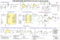
But we need a more reliable approach, since the injector we are using is peak and hold diesel injector. Currently we referred few sources and built a circuit, which resembles something like in the image. But is there any better way to read the signal and controlling the injector pulses using a microcontroller?


circuit.png
Google Docs

150042.png
 
Last edited by a moderator:
The Texas Instruments LM1949 IC was specifically designed for firing and holding low impedance injectors. Not sure if it's obsolete, certainly still available, not necessary with newer high impedance injectors.
 

Thread Starter

harshan16

Joined Aug 29, 2026
5
The Texas Instruments LM1949 IC was specifically designed for firing and holding low impedance injectors. Not sure if it's obsolete, certainly still available, not necessary with newer high impedance injectors.

Yes I have similar experience,
I have an injector setup which uses the diesel injector, currently Im using MOSFET to control the low side of the injector. The high side is connected to constant supply 12v SMPS. Now I'm able to control the injector with this setup. But I faced 2 issues,
1) I lost 2 injectors due to this approach, not in a single use. But after prolonged testing.
2) in idling of engine, by tapping the engine's injector pulses and mirroring it to the MOSFET which controls the injector, I got around 90ml of diesel for 60seconds. Which seems very unrealistic.
 

Thread Starter

harshan16

Joined Aug 29, 2026
5
Hi there, I'm basically working in a project where we are building a dual fuel injection system. For prototyping we are tapping the injection pulse of a fuel injector of a running engine and reading it via optocoupler and actuating another injector by pulse read by a microcontroller. We used Arduino for first stage of prototype, where the Arduino gets digital input from the optocoupler and adjusts the pulse width and gives out as output in a digital pin, which is connected to a MOSFET's gate pin. The drain and source pin of the MOSFET are connected between the injector's control line.

But we need a more reliable approach, since the injector we are using is peak and hold diesel injector. Currently we referred few sources and built a circuit, which resembles something like in the image. But is there any better way to read the signal and controlling the injector pulses using a microcontroller?


circuit.png
Google Docs


View attachment 370857
I have an injector setup which uses the diesel injector, currently Im using MOSFET to control the low side of the injector. The high side is connected to constant supply 12v SMPS. Now I'm able to control the injector with this setup. But I faced 2 issues,
1) I lost 2 injectors due to this approach, not in a single use. But after prolonged testing.
2) in idling of engine, by tapping the engine's injector pulses and mirroring it to the MOSFET which controls the injector, I got around 90ml of diesel for 60seconds. Which seems very unrealistic.

The circuit is a rough idea, but please give some of your approach in working with this project.
 
At all times, fuel injector timing and duty cycle are very important!! Check the manufacturer's specifications. DRY operation is not recommended!!!
As the TS has discovered, it is easy to overheat and damage injectors, which are cooled by fuel flow in normal application. The BETTER QUALITY injector test stands are able to protect the items being tested against overheating damage.
 

du00000001

Joined Nov 10, 2020
200
Yes I have similar experience,
I have an injector setup which uses the diesel injector, currently Im using MOSFET to control the low side of the injector. The high side is connected to constant supply 12v SMPS. Now I'm able to control the injector with this setup. But I faced 2 issues,
1) I lost 2 injectors due to this approach, not in a single use. But after prolonged testing.
2) in idling of engine, by tapping the engine's injector pulses and mirroring it to the MOSFET which controls the injector, I got around 90ml of diesel for 60seconds. Which seems very unrealistic.
90 ml/Min would translate to 5.4 l/h. What kind of motor is this ? No of cylinders, displacement, power, rpms in idle, what kind of injection system ?
For a truck or a smaller ship this might be ok, for a passenger car certainly not.

Did you MEASURE these 90 ml/Min or did you just calculate this value via the pulse width ? Some injection systems (resp. the injectors) take an itsy-bitsy ONE ms (some even more) from the start of the pulse to the start of the injection. (1 ms sounds much, but considering that for a 4-stroke 4-cylinder engine the "cylinder-frequency" for 6000 rpms (crankshaft) is a meager 50 Hz, you have 20 ms for each cylinder to position and execute your injection. And the fuel delivery rate for high rpms can be astonishing high ;)
 
Top