Facebook
 Google
 GitHub
 Linkedin
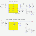
Ok Ron ill go over it today.Maybe if the output voltage approaches zero. The requirement is 10 to 18V.
LATER:
Ok i took a quick look at this and what i quickly realized is we dont really know what the output is unless we measure it. In other words, when we change the controlling voltage it does not tell us what the output is so most likely we'd have to measure it. That means we cant do a full analysis until we know what changes the controlling voltage because that would be part of the feedback.
It might be possible to correlate the output of the DAC to the output, but that's not as good as actually measuring the output and adjusting the controlling voltage accordingly.
What this means is we would have to know the program code that does that alters the controlling voltage.
Last edited: