Constant Current Mesh Network

Thread Starter

deval vyas

Joined May 10, 2016
3
Hi,

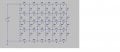
I am trying to build a constant current mesh network. In the attached diagram, I would like to have current in all the vertical resistances- R1 to R 28 to be same and in the same direction. I want to do this for a n X n mesh even though the picture shows only a 6x4 mesh. How can I do it? Is there a formula that can be derived which can be applied to an n X n mesh? All the horizontal resistance R29 to R58 as well as current in these horizontal resistances are variables but the current in R1 to R28 have to be same.


Thanks
Deval
 

Attachments

Roderick Young

Joined Feb 22, 2015
408
Take a look at the junction of R3 - R10 - R36 - R37. If R3 and R10 have the same current flowing, then R36 and R37 can have no net contribution to their current. That's another way of saying that the current in R36 and R37 doesn't matter, as long as it's the same. So might as well choose 0. Remove R36 and R37.

After making similar removals, maybe there will be a pattern?
 

DGElder

Joined Apr 3, 2016
351
Hint: The solution is simple. Apply what you have learned about basic circuits and think it through logically.
 
Last edited:

Thread Starter

deval vyas

Joined May 10, 2016
3
Thanks for the reply....unfortunately i cant remove horizontal resistances R36, R37 etc. I need to adjust the resistances such that current remains same.

i have already worked out a solution for n x 1 ladder network..but n x n is challenging.

is there any network analysis software that can give me value of resistance if i feed in the value of current?

I am currently using LTSpice IV, but here the resistors are variables and the system calculates current. is there any way i can specify the current and the software can calculate resistances necessary to get those currents?

manually analysis of each loop might be too time consuming...
 

DGElder

Joined Apr 3, 2016
351
I think you are missing the point of the exercise. I assume this is a homework assignment. If you give it some thought you will realize the solution is trivial. But the mental gyrations you will go through to realize this are meant to develop circuits insight, not to have you solve some complex mesh equations.

What are the voltages on the Vertical Resistors?
 

Thread Starter

deval vyas

Joined May 10, 2016
3
I am more concerned about keeping current similar in the branches by manipulating the resistances...the voltage and the value of resistors are variables...there will only by one voltage source though...

i guess i will have to analysis using mesh/branch current analysis. its not a HW assignment but i am working on a project involving fluidics..and each of the resistances re-present actual fluidic resistances of channels... the analysis is similar to mesh analysis of electrical networks...

is there any software where i can simulate this? as there are going to be many iterations in my design...
 

DGElder

Joined Apr 3, 2016
351
You said the vertical resistors all had equal resistance and current. This can only happen if all the horizontal resistors = zero. The voltage (pressure if you prefer) in all the vertical resistors (pipe) = V1/4
 
Last edited:

Roderick Young

Joined Feb 22, 2015
408
If this is a real-life situation, let me be more direct. You cannot equalize the current in this manner. If you must control the current in the vertical resistors, put an additional resistor in series with each string.
 

DGElder

Joined Apr 3, 2016
351
If you use this basic topology, you should modify it by removing all the inner horizontal pipes since they do nothing - as Roderick pointed out earlier. Minimize the resistance in the outer horizontal pipes to minimize loss of pressure between columns and you will need to incrementally decrease the resistance of the vertical pipes as you move from the left column to the right column in order to get equal fluid (current) flow in each column - if that is your main objective. Presumably you would do this by using incrementally larger diameter pipes but I have no idea what you are trying to accomplish - and I am not a Chemical Engineer anyway. The greater the outer horizontal resistances, the greater the resistance difference in each vertical column you will need. The limit case, and perhaps unrealizable case, is if they have zero resistance, then all the pipes in the vertical columns will need the same size (resistance).

I think you only have 3 independent variables in the design: V1, Iv, Rh.
Easy to figure and from that you can easily get Rvs.

If you are serious about this you ought to layout more detailed objectives and constraints of your project and take it to a Chemical Engineering forum. They have the requisite expertise in fluid dynamics. Have fun.
 
Last edited:

WBahn

Joined Mar 31, 2012
29,979
The trivial solution.

1) Set all vertical resistances to the same value.
2) Set all horizontal resistances in the top and bottom levels (the peripheral horizontal resistors) to zero.
3) Set all other horizontal resistances (the interior horizontal resistors) to infinity.

If you want a solution in which all of the horizontal resistance are finite and strictly positive, then you have to look at the constraints that MUST be met and then consider what level of freedom you have within those constraints.

Since you want the current in all of the vertical resistors to be the same, there must be no current flowing in any of the interior horizontal resistors. If these are not infinite, then the only way to achieve this is for the voltages on all of the nodes at a given horizontal layer to be the same so that there is no voltage drop across any of the horizontal resistors in that layer. Since the vertical current is the same for all of the vertical resistors, this further requires that all of the resistors connecting one interior horizontal layer to an adjacent interior horizontal layer have to be the same value (though they don't have to be the same value as the resistors that connect other adjacent interior horizontal layers.

That leaves you with two remaining sets of resistors:

Set #1: the top layer of horizontal resistors and the top most set of vertical resistors.
Set #2: the bottom layer of horizontal resistors and the bottom most set of vertical resistors.

By symmetry, whatever constraints apply to the top set can be used for the bottom set (but arbitrary parameters don't need to be the same between them). So let's focus on the top of the circuit.

So let's consider the following re-labeled version of your circuit:

R-mesh.png

The resistors at the top are numbered such that the odd numbered resistors are vertical and the even numbered resistors are horizontal. Furthermore, the vertical resistor connected to Node Ni(where i is between 0 and 7 in this case) is R_(2i+1) while the horizontal connected to the right of it is R_2i.

KVL requires that the following constraint be satisfied at each node Ni for i > 0.

\(
I_0 R_{\( 2i+1 \)} \; = \; i I_o R_{\( 2i \)} \; + \; I_o R_{\( 2i-1 \)}
\)

This imposes a recurrence relation among the resistors of:

\(
R_{\( 2i+1 \)} \; = \; i R_{\( 2i \)} \; + \; R_{\( 2i-1 \)}
\)

that must be satisfied for all i > 0 -- for the case of i = 0, we see that R_1 must equal R_-1, which doesn't exist. Here, this means that we can set R_-1 to anything we want, which effectively means that we can choose an arbitrary value for R_1.

Notice what this relation says -- that the value of each odd-numbered resistor is related to the value of an even-numbered resistor and the prior odd-numbered resistor. So once we pick the value of the first odd-numbered resistor the subsequent odd numbered resistors are determined for us.

But we don't have a relationship for the even-numbered resistors, meaning that we can choose them arbitrarily (as long as we don't end up making some relationship physically unrealizable). It would be nice to make that pesky 'i' go away, so what if we make

\(
R_{\(2i\)} \; = \; \frac{R_{\( 2i-1 \)}}{i}
\)

In other words, each even-numbered resistor is equal to the odd-numbered resistor on its right divided by the number of the node on its left. This (arbitrary) choice results in the recurrence relation for the odd-numbered resistors becoming

\(
R_{\( 2i+1 \)} \; = \; 2 R_{\( 2i-1 \)}
\)

Which is equivalent to

\(
R_{\( 2i+1 \)} \; = \; 2^i R_1
\)

Note that this holds for all i greater than or equal to zero.
 
Top