CONSTANT AC CURRENT SOURCE

Thread Starter

Luvo

Joined May 13, 2021
11
Hello,

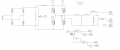
I have been tasked to design an ac constant current source for my school project. The specifications of the design are:
  1. The current source should output 0-16 Amps
  2. The output frequency of 60-1800 Hz
  3. The output power of 1000 VA
  4. The input voltage 230V @ 60 Hz
  5. THD 10% -15%
  6. Current regulation of 5% - 15%
  7. The output should be sinusoidal
FOR THIS DESIGN THE CURRENT SHOULD NOT VARY WITH THE LOAD, THIS MEANS IF YOU CHANGE THE LOAD YOU SHOULD STILL MAINTAIN A CONSTANT CURRENT

So my approach was to couple the rectifier with the inverter circuit and use PWM to control the output current and frequency, but my design is not working and I am failing to design a control loop for the circuit. Can someone please help

Your help will be much appreciated

regards
Luvo
 

Papabravo

Joined Feb 24, 2006
21,159
Were you assigned this project, or did this just seem like a cool thing to do. I'm not convinced it has any utility at all.
In particular there are some changes in the LOAD that will absolutely prevent you from forcing a fixed current into that load.
I'm not surprised that you are having trouble.
Maybe you would care to share your schematic with us.
 
Last edited:

Papabravo

Joined Feb 24, 2006
21,159
Yes I am assigned to this project and I could not solve it, if you could please help
I think you need to start by understanding your limitations. There are some conditions that you cannot satisfy.
Besides the general complaint that it is not working, can you be more specific about exactly what is not working. that way we can determine if you are up against an impossible situation or just a momentary impediment.
 

Thread Starter

Luvo

Joined May 13, 2021
11
I think you need to start by understanding your limitations. There are some conditions that you cannot satisfy.
Besides the general complaint that it is not working, can you be more specific about exactly what is not working. that way we can determine if you are up against an impossible situation or just a momentary impediment.
with what I have so far the current keeps changing as I vary the load
 

Papabravo

Joined Feb 24, 2006
21,159
The voltage is not changing
the schematic is attached below
This is Ohm's law at work. You cannot change the load impedance and EXPECT the voltage AND the current to remain the same. This is what I meant by adjusting your expectations. One of them has to change for the other one to remain constant. I really don't know how to do what you are describing.

The use of non-standard symbols makes this schematic difficult to interpret.
 
Last edited:

Papabravo

Joined Feb 24, 2006
21,159
Definitely AC output - it's an audio amplifier!
I'm starting to wonder about this whole concept. An audio amplifier has limits imposed by the power supply, but it does not try to regulate both the current and the voltage at the same time. It is a good thing that it doesn't try because it can't do that.
 

Thread Starter

Luvo

Joined May 13, 2021
11
This is Ohm's law at work. You cannot change the load impedance and EXPECT the voltage AND the current to remain the same. This is what I meant by adjusting your expectations. One of them has to change for the other one to remain constant. I really don't know how to do what you are describing.

The use of non-standard symbols makes this schematic difficult to interpret.
The voltage needs to change as the load changes but what should remain constant is the current
 

Ian0

Joined Aug 7, 2020
9,679
The output voltage is conspicuously absent from the spec!
Control loops for power supplies/amplifier are seriously difficult to design in the digital domain, much simpler in analogue.
I see a third-order filter in the diagram in post #5, which has 270° phase shift - I see the beginnings of an oscillator. . . . .
 

Thread Starter

Luvo

Joined May 13, 2021
11
The output voltage is conspicuously absent from the spec!
Control loops for power supplies/amplifier are seriously difficult to design in the digital domain, much simpler in analogue.
I see a third-order filter in the diagram in post #5, which has 270° phase shift - I see the beginnings of an oscillator. . . . .
With the filter, I was trying to minimize the harmonics to cater for 15% THD in the specs
 

Ian0

Joined Aug 7, 2020
9,679
If you have more than 180° phase shift inside the control look it's going to oscillate
(by the way, the circuit in post #11 would manage better than 0.1% THD)
 

Thread Starter

Luvo

Joined May 13, 2021
11
If you have more than 180° phase shift inside the control look it's going to oscillate
(by the way, the circuit in post #11 would manage better than 0.1% THD)
can you please help how should I modify the circuit in post #11 to meet my specifications
 
Top