Hello all. I've been researching for weeks trying to learn as much as I can on the subject but have hit a wall. I have an existing setup for a funicular elevator - worked fine for a decade but the motor recently died. Found a replacement motor with identical specs but can't figure out how to wire it up (the wiring is slightly different on the new one).
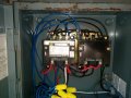
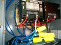
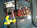
The system has two Square D Nema 0 type S mechanical starters with the accompanying wiring diagram.

The problem I'm having is that the motor I'm using is a single phase induction-start induction-run motor. I understand that to reverse the direction is a matter of reversing the polarity of starting winding with respect to the run windings, but I can't for the love of me figure out how to map the (3) outputs of the starters to the (6) motor leads as seen below.

The starters are wired to 240 with i1 and i2, and outputs O1, O2, O3 (I apologize in advance for incorrect nomenclature or conventions) coming off the bottom of the relays. When latched in the forward position O1 = O2 = i1 and O3 = i2, when in reverse O1 = i1, and O2 = O3 = i2. I've probed the various contacts exposed on the relays to see if there's anything else I could use - but I think most of them are part of the 'latching circuit' and not intended to drive the motor.
I've probed the motor and P1-2, 3-4 and 5-8 appear to have continuity (although 5-8 behave strangely on the multimeter with the resistant slowing going up - I assume because of interaction with a capacitor).
It was all working perfectly with nearly identical motor, so i know it's possible - just reached the limit of my understanding.
I appreciate any insight,
Shaun
The system has two Square D Nema 0 type S mechanical starters with the accompanying wiring diagram.
The problem I'm having is that the motor I'm using is a single phase induction-start induction-run motor. I understand that to reverse the direction is a matter of reversing the polarity of starting winding with respect to the run windings, but I can't for the love of me figure out how to map the (3) outputs of the starters to the (6) motor leads as seen below.
The starters are wired to 240 with i1 and i2, and outputs O1, O2, O3 (I apologize in advance for incorrect nomenclature or conventions) coming off the bottom of the relays. When latched in the forward position O1 = O2 = i1 and O3 = i2, when in reverse O1 = i1, and O2 = O3 = i2. I've probed the various contacts exposed on the relays to see if there's anything else I could use - but I think most of them are part of the 'latching circuit' and not intended to drive the motor.
I've probed the motor and P1-2, 3-4 and 5-8 appear to have continuity (although 5-8 behave strangely on the multimeter with the resistant slowing going up - I assume because of interaction with a capacitor).
It was all working perfectly with nearly identical motor, so i know it's possible - just reached the limit of my understanding.
I appreciate any insight,
Shaun

")