Facebook
 Google
 GitHub
 Linkedin
Hello everyone! Does anyone in here have any experience with older Mecc Alte generators?
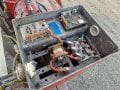
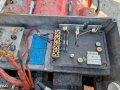
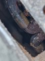
So, im trying to revive this old diesel genset. Imo the whole unit is basically trash, it's an old marine generator and the sea did not let it go without a fight. Corrosion is rampant, as you see in the pictures. But my customer really wants me to fix this unit, something about his father having worked on it or whatever. And like a miracle, all insulation tests are fine, so maybe there is hope after all?
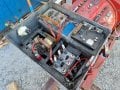
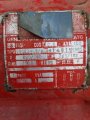
But the AVR seems dodgy to say the least. I dont trust it, and i dont want any overvoltage events ruining his equipment in the future. And i need to change the output voltage from 400Vac to 230Vac anyway, so im replacing the old AVR. But im very confused with the wiring, and i'd like to have a general understanding on how this actually works before i start experimenting with it.
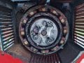
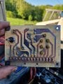
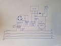
I made a wiring diagram showing the old wiring, to my best knowledge. Unlike any other AVR i've ever worked on, there does not seem to be any feeback of the actual output voltage to the AVR. Im assuming the "S" winding, being fused and having thicker wires, is for powering the AVR itself. Then the 8 ohm load must be the windings in the magnetizing field stator, this being a brushless generator. Unfortunately i dont have a proper instrument which can measure inductance on hand right now, so i can only measure resistance.
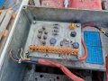
But then there's the current transformer thing, connected to its own 8 ohm load. Could there be two separate windings in the magnetizing field stator? it's so weird. Im tempted to connect a variable dc supply to these 8 ohm loads while the machine is running and see what happends, but the pucker factor is a bit too high still.
Anyone want to weigh in on this? Im looking forward to hearing from you.
Thank you all for your attention, i wish you a nice day.
So, im trying to revive this old diesel genset. Imo the whole unit is basically trash, it's an old marine generator and the sea did not let it go without a fight. Corrosion is rampant, as you see in the pictures. But my customer really wants me to fix this unit, something about his father having worked on it or whatever. And like a miracle, all insulation tests are fine, so maybe there is hope after all?
But the AVR seems dodgy to say the least. I dont trust it, and i dont want any overvoltage events ruining his equipment in the future. And i need to change the output voltage from 400Vac to 230Vac anyway, so im replacing the old AVR. But im very confused with the wiring, and i'd like to have a general understanding on how this actually works before i start experimenting with it.
I made a wiring diagram showing the old wiring, to my best knowledge. Unlike any other AVR i've ever worked on, there does not seem to be any feeback of the actual output voltage to the AVR. Im assuming the "S" winding, being fused and having thicker wires, is for powering the AVR itself. Then the 8 ohm load must be the windings in the magnetizing field stator, this being a brushless generator. Unfortunately i dont have a proper instrument which can measure inductance on hand right now, so i can only measure resistance.
But then there's the current transformer thing, connected to its own 8 ohm load. Could there be two separate windings in the magnetizing field stator? it's so weird. Im tempted to connect a variable dc supply to these 8 ohm loads while the machine is running and see what happends, but the pucker factor is a bit too high still.
Anyone want to weigh in on this? Im looking forward to hearing from you.
Thank you all for your attention, i wish you a nice day.
Attachments
-
 3.6 MB Views: 19
 -
 4.6 MB Views: 24
 -
 4 MB Views: 20
 -
 4.1 MB Views: 21
 -
 1.8 MB Views: 18
 -
 1 MB Views: 16
 -
 2.3 MB Views: 17
 -
 3.2 MB Views: 18