Confused about Floating Voltages and Stray/Parasitic Phenomenon

WBahn

Joined Mar 31, 2012
33,072
Welcome to AAC, Kiss!

Just to let you know, AAC is a privately owned enterprise. There are two sides to AAC which began as a free not-for-profit open platform for electronics hobbyists and professionals alike. The owners have ventured into the for-profit commercial advertisement side and are not too keen to allow other parties to promote there own enterprise.
Though this was the case even before the other side went commercial. If we allow site promotion posts, then we will get flooded with nothing but site promotion posts.

We DO have several people that post here who have commercial interests and who largely post only on topics that align with those interests. They have learned to walk the fine line of contributing their expertise while avoiding promoting their businesses. It's not always possible and sometimes they feel that the only way to contribute is to cross that line. This is where reputation comes in. If they have established a reputation as a member that is here to help members, the moderation staff is much more likely to view occasional line crossings as coincidental and not intentional site promotion. Hopefully you can understand that new members are not given the benefit of the doubt on this, if only because we regularly get new members who join clearly for the purpose of promoting their site. It takes some time to build the necessary reputation.
 

Thread Starter

Ray CJ

Joined Apr 30, 2023
11
One thing to keep in mind is that as soon as you connect your scope probe's ground to any point in the secondary of the circuit, that circuit is no longer floating -- it is now ground referenced, via the scope, to the earth conductor of it's power cord (unless the scope is battery powered, of course). If you NEED the circuit to be floating, then do NOT make this connection. More to the point, if you do make this connection, be very sure that there is no point elsewhere in the circuit that is somehow, intentionally or otherwise, referenced to earth ground. If there is, then at best you have created a ground loop situation that can wreak havoc with noise pickup, and at worst you have created a short across part of your circuit that could potentially (no pun intended) have disastrous results. If you need the circuit to remain floating, then you need to use a battery powered scope or a scope with differential inputs (neither common nor cheap) or a suitable differential amplifier between your circuit and your scope.
Thank you... -And I do appreciate the note of concern. I use active differential probes most of the time -especially on anything I'm not familiar with. Also, before I touch a passive probe to any circuit, I double and triple check until I fully understand the DUT. So far, so good. Knock on wood, I have not fried any equipment (yet).

Ray
 

Thread Starter

Ray CJ

Joined Apr 30, 2023
11
It's the transformer!

Well, it seems the amplitude of the waveform is entirely dependent on which transformer is used. Four different 12V transformers (connected to the same bridge-rectifier and smoothing cap) produced 4 wildly different amplitudes. For all 4 transformers, the shape of the waveform was basically the same.

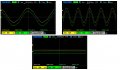
The DC output (from neg to pos) is just fine. Here are some images using just one of the transformers. In all the images below, one probe is on the DC+ terminal, another probe is on the DC- terminal and the probe grounds are connected to Earth ground. In this common-mode reading, it's clear that with this particular transformer, the secondary winding is moving up/down on an AC signal (with respect to ground). Of course, if I ground either of the secondary terminals, the waveform goes flat.

In the bottom image, the reading is from a lab supply set to 12V DC. The ground lug on that supply is not connected to ground but, the unit has (of course) a 3 prong plug.

I think one of the previous posters hit the nail on the head. It seems this is caused by capacitive coupling between the windings of the transformer. The lab supply obviously has addressed that problem.

ItsTheTransformer.JPG
Ray
 

KeithWalker

Joined Jul 10, 2017
3,614
Does the amplitude change if you reverse the power connections to the primary? A toroidal transformer may not show much difference, depending on how it is constructed but there should be more on an unshielded transformer with laminations.
 

Thread Starter

Ray CJ

Joined Apr 30, 2023
11
I'll give that a try tomorrow.
Well Keith, that certainly makes a difference. After reversing the primary connections, the waveform shown in post #23 went from 43V to 62V. I have an LCR meter and will do some reading about transformer measurements.

Thanks

Ray CJ
 

KissAnalog

Joined May 1, 2023
2
I will do this in the lab, but just to see if I can help - I'll offer this explanation:
You have to remember that your scope has Y caps from each Line and Neutral to Chassis ground, so if you were to place a scope probe from chassis ground to Line or Neutral - you simply see the voltage across these capacitors. These capacitors are relatively small in value so do have some impedance and work against the impedance in the CM choke, so there is some voltage division. When you probe on the secondary side of a transformer - it is not truly floating. It is galvanically isolated, but this is in the DC domain, and in the AC domain - there is some signal. This signal is transferred - as you predicted in the first of this message as parasitics... There is parasitic capacitance in the transformer - so you will see an AC voltage when you probe the secondary side. Now when you place that 1 uF cap - it goes away - kind of. It is really just reduced to a small value as it is now in a voltage divider between the components on the primary side and the parasitic capacitance across the secondary to this new relatively large capacitor - which is relatively low in impedance - thus the low voltage reading. This is why power guys will 'float' their oscilloscope - to get away from this erroneous measurement... Make sense? Isolate your scope and watch the magic;)
 

Thread Starter

Ray CJ

Joined Apr 30, 2023
11
I will do this in the lab, but just to see if I can help - I'll offer this explanation:
You have to remember that your scope has Y caps from each Line and Neutral to Chassis ground, so if you were to place a scope probe from chassis ground to Line or Neutral - you simply see the voltage across these capacitors. These capacitors are relatively small in value so do have some impedance and work against the impedance in the CM choke, so there is some voltage division. When you probe on the secondary side of a transformer - it is not truly floating. It is galvanically isolated, but this is in the DC domain, and in the AC domain - there is some signal. This signal is transferred - as you predicted in the first of this message as parasitics... There is parasitic capacitance in the transformer - so you will see an AC voltage when you probe the secondary side. Now when you place that 1 uF cap - it goes away - kind of. It is really just reduced to a small value as it is now in a voltage divider between the components on the primary side and the parasitic capacitance across the secondary to this new relatively large capacitor - which is relatively low in impedance - thus the low voltage reading. This is why power guys will 'float' their oscilloscope - to get away from this erroneous measurement... Make sense? Isolate your scope and watch the magic;)
Excellent info Eddie... This fills-in all the remaining details.

Ray
 
Top