Oh yes that makes more sense.
It looked like he was using sine waves though.
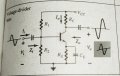
Come to think of it, those two do not look right either because of the input and output capacitors. It must create a wave that has a measurable phase shift.
Not really. Look at the actual explanation he is asking about (and that I was specifically responding to): " is the current flow theough collector resistor being halted somehow for which output signal voltage lags behind of input "
If I tell you I have a phase shift of 180 degrees in a signal I would think you would know what I mean.
Sure there is -- an inversion is a multiplication by -1 independent of frequency. Phase shifts are almost always frequency dependent and are only 180° at a particular frequency.
Also, I would think that any periodic waveform can be considered to be phase shifted but perhaps not inverted. Thus calling it an "inverter" may not be entirely correct either.
Trivial to show that this is not the case. Consider a DC waveform of 10 V. What does that look like if it is inverted? What does it look like if it is shifted by 180°?
I think what we are talking about here is how the circuit is USED. In your example I think it would be better to call it an inverter. If we have positive pulses going in, we get negative pulses out. With sine waves, as was illustrated in the first post, i think we could call it either an inversion or a phase shift.
Remember we are really talking about the measurements vs the application.
We measure phase shifts, we implement circuits.
We are trying to help the TS understand the concept they are inquiring about, which very specifically included proposed claim that the observed output is the result of current being halted and delayed in a resistor.
Are you REALLY okay with letting that explanation stand as their understanding?
Nowhere does he say he is using sine waves. He never mentions a sine wave, even as an example.
From their first post: " it has come to my notice that there is a 180 degree phase shift between input and output signals.My question is-Can anyone explain why is there a phase shift? "
From their second post: " what is physically happening inside of the circuit?I mean is the current flow theough collector resistor being halted somehow for which output signal voltage lags behind of input? "
He is asking about the relationship between any input signal and any output signal. He is asking what is actually happening in the circuit. He is asking if his explanation for what is happening is correct.
Come to think of it, those two do not look right either because of the input and output capacitors. It must create a wave that has a measurable phase shift.
Yes, but it is hopefully pretty negligible at signal frequencies. Discussions are generally assumed to be focused on the passband unless it is pretty clearly indicated, either explicitly or via context, to be otherwise.
The input capacitor creates a high pass filter that has very little phase shift well above the cutoff frequency. The same for the output capacitor. If they are operating at a frequency that is close enough to the corner frequencies that the phase shift is significant (and will still only be 90° at the cutoff frequency, assuming they are both the same), then the effect on amplitude is going to significant enough to be worth discussing.
Nowhere does he say he is using sine waves. He never mentions a sine wave, even as an example.
From their first post: " it has come to my notice that there is a 180 degree phase shift between input and output signals.My question is-Can anyone explain why is there a phase shift? "
From their second post: " what is physically happening inside of the circuit?I mean is the current flow theough collector resistor being halted somehow for which output signal voltage lags behind of input? "
He is asking about the relationship between any input signal and any output signal. He is asking what is actually happening in the circuit. He is asking if his explanation for what is happening is correct.
Yes, but it is hopefully pretty negligible at signal frequencies. Discussions are generally assumed to be focused on the passband unless it is pretty clearly indicated, either explicitly or via context, to be otherwise.
The input capacitor creates a high pass filter that has very little phase shift well above the cutoff frequency. The same for the output capacitor. If they are operating at a frequency that is close enough to the corner frequencies that the phase shift is significant (and will still only be 90° at the cutoff frequency, assuming they are both the same), then the effect on amplitude is going to significant enough to be worth discussing.
He never mentions a sine wave?
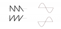
Then what are those two wave shapes seen in the original diagram?
I redrew the diagram with the input wave right under the output wave. If they are not sine waves then I don't know what they are.
The interpretation can be either inversion or phase shift there's no way around that.
Um, that is the difference between even and odd harmonics. Odd will be shifted by 180 when the base frequency is, even will be shifted by 0 (same as 360). It is not a coincidence that all odd harmonics see a 180 shift, it is mathematics.
He never mentions a sine wave?
Then what are those two wave shapes seen in the original diagram?
I redrew the diagram with the input wave right under the output wave. If they are not sine waves then I don't know what they are.
The interpretation can be either inversion or phase shift there's no way around that.
Um, that is the difference between even and odd harmonics. Odd will be shifted by 180 when the base frequency is, even will be shifted by 0 (same as 360). It is not a coincidence that all odd harmonics see a 180 shift, it is mathematics.
No one is disputing that an inversion and phase shift of 180 are identical for a sine wave.
But the question was about why the output of a CE amplifier is inverted. Do you think CE amplifiers can be used only for pure sine waves?
Of course not, why would you even ask that question after I had shown an inverted sawtooth as per your suggestion?
It's starting to look like there has just been a number of misunderstandings between individuals in this thread and different interpretations. I do not see any point in discussing this any further because it depends on interpretations and semantics. It was interesting though thanks.
 Facebook
 Google
 GitHub
 Linkedin