 Facebook
 Google
 GitHub
 Linkedin
Hi,
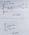
The 3 way splitter, 100MHz 6A power pass was used in TV cable line. Out 1 has DC voltage output too with RF. Out 2 and Out 3 has just RF output.
The circuit of the splitter looks complex to me. I used to imagine there are only two capacitors inside as uploaded circuit. But look at the real splitter, it has nice design.
Just curiosity: what is the job of the complex circuitry there?
Attachments
-
 1.1 MB Views: 17
 -
 2.1 MB Views: 18


