 Facebook
 Google
 GitHub
 Linkedin
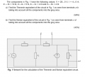
Hi guys, ive recently had a loss and ended up leaving something last minute. i just seem to be having issues with this problem and it will determine wether or not i get into third year engineering. if anyone has seen this problem before or has the expertise to solve it i would be extremly grateful.
Attachments
-
 40.4 KB Views: 14


