Facebook
 Google
 GitHub
 Linkedin
I just posted another thread about this circuit on relay switching and now I realize that relay switching is not my issue but rather a lack of understanding on how this circuit works. So I started another thread to discuss how this circuit works.
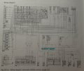
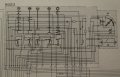
I went and tested my all stock all working 560SL which is wired exactly according to the diagram below and realized that I do not understand how that works at all.
Looking at the diagram below, I would have assumed that if I pulled the 0.75 BK/RD wire off the B10/6 Evaporator temps sensor, and measured voltage at the end of the wire, I would get ~13 volts with the AC in either Norm, TV or Defrost positions. I did not, I got 0 no mater what I did Key off, key on AC of or AC on. This originally led me to believe that my push button control unit was bad. But its also like that on the stock 560SL I just tested which works perfectly.
Also looking at the diagram below, I would have assumed that if I pulled the 0.75 BK/RD/GN wire off the opposite side of the evaporator temp switch, I would get 0 volts, I do not, I get ~ 13V with the key on and the AC in either on or off. This led me to believe my Base module was bad. Except this is the same performance I get on my stock 560SL which performs perfectly. The actual performance on the stock 560SL was ~13.3 volts with the AC off and ~12.4 Volts with the AC on.
So the question is 1) Why is there no voltage at the 0.75 BK/RD wire at the B10/9 temperature sensor at any time. 2) Where does power come from on the other side of the B10/9 temperature sensor 0.75 BK/RD/GN wire.
I also did check that the wire BK/RD wire was going to terminal 6 of the push button control. Keep in mind the push button control is not a manual switch as shown but more of a relay controlled switch.