I am afraid that I cannot read all of your writing.
It would be better if you typed out all of your assumed formulas and calculations.
For example, is that Voutavg=103.45v and is that mentioned to indicate the conduction phase?
I've highlighted some of the symbols that are hard to read.
Yes, that was inferred from the 103.45v average considering zero voltage drop for the rectifiers.
However, I think the average is really 103.54v so maybe you accidentally swapped the 4 and the 5 in your "103.45v" quote.
I am afraid that I cannot read all of your writing.
It would be better if you typed out all of your assumed formulas and calculations.
For example, is that Voutavg=103.45v and is that mentioned to indicate the conduction phase?
I've highlighted some of the symbols that are hard to read.
I'm very sorry, thank you very much for the hint. And you are also right about the voltage of 103.54 V.
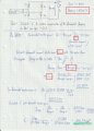
Your marked points from top to bottom:
1) Vout,avg. = 103.54 V (average value of the output voltage across the inductance and the resistance)
2) Just a hint for the current I1.1, which still needs to be calculated.
3)I1.1 is the fundamental component of the current coming from the mains.
4) Vrms,grid is the mains voltage (RMS Value)
5)I1.1 is the fundamental component of the current coming from the mains.
I'll type out what is on the sheet again:
My Solution : Fundamental reactive power: Q1 = Vrms,grid * I1.1 * sin( φ1 )
Calculate fundamental component of the current I1.1 with the active Power:
Assumption: Bridge rectifier is losless! Then P = P1 (P is "normal" active power and P1 ist is the fundamental component of the active power)
P = Vout,avg. * Iout
P1 = Vrms,grid*I1.1*cos( φ1 )
and P = P1
Vout,avg. * Iout = Vrms,grid * I1.1*cos( φ1 ) -> convert to I1.1
I1.1 = (Vout,avg *Iout)/(Vrms,grid * cos( φ1 )) = (103.54 V *40A) / (230V * 0.8) = 22.5 A
Fundamental reactive Power: Q1 = Vrms,grid * I1.1 * sin( φ1 ) = 230V *22.5 A * 0.6 = 3105 var
Calculate now C with fundamental reactive Power:
Icap.= Qc/Vrms,grid = Q1/Vrms,grid = 3015 var / 230V = 13.5A
C = Icap /2*pi*50*Vrms,grid = 13.5A/(2*pi*50*230) = 186.743uF.
Ok great thanks for the clarification.
I'll see if I can do something with this unless someone else gets back here first.
It's a little interesting that these issues did not come up that much in the distant past. It's relatively recent that attention to power factor became more important, at least more so than back in the distant past. I guess with very high power applications it was always something to think about though, but with computer power supplies and stuff like that it's also become a concern.
The only complication here is that the conduction angle is not 180 degrees and that may bring in some other issues.
I tried it once but it was connected to a generator. It wasn’t a great success, to say the least.
Firstly, the generator shuts down if it finds a leading power factor, and secondly the fast edges from the phase firing circuit triggered a resonance between the capacitor and inductor, which made such a mess of the current waveform that the generator AVR could no longer detect zero crossing and then couldn’t keep a steady speed.
Eventually concluded that the generator preferred a bad power factor over my attempts to correct it!
You may be more successful on the mains!
Oh right, there are times when it would be bad to try to correct the power factor using a capacitor such as on the output of an inverter. I could imagine a generator would have a problem with this too. I've seen a case where the generator would not be able to start a motor due to the motor start current too. Power lines are probably not subject to this kind of thing unless we really overdo it.
I looked at your calculations again, and see that the definition for power factor cos(angle) you were using is more for sinusoidal waveforms, so let's look at a more general definition of power factor, then see what you can do with this from here. If you have any problems I'll surely get back here again at a later time.
A more general definition is:
PF=Vavg/(Vrms*Irms)
and we know the definition of Vavg and Vrms and Irms:
Vavg=integrate(v*i,t,0,Ton)/Tp
Vrms=sqrt(integrate(v^2,t,0,Ton)/Tp)
Irms=sqrt(integrate(i^2,t,0,Ton)/Tp)
A few notes about the above...
1. 'v' and 'i' are functions of time t so they are really v(t) and i(t).
2. Tp is the total period (usually of a half cycle).
3. Ton is the total 'on' time.
In the above Tp is the total period but you have to select the integration period so that it encapsulates one period, and that period may have to be discovered carefully when computing the Vavg. A graph of v*i would help to determine that. The start time may not be zero but may start at some other time t1. It's not likely to start at zero because of the way the switching devices work.
Ton is the total 'on' period for the time the output is turned on, and this resides within the Tp period. This period may not start at zero as shown but may go from some time t2 to another time t3. If you can't visualize this try doing a graph.
When integrating we often show the integration period as going from t=0 to t=Tp and that is certainly valid, but often some parts of the waveform at at zero for a period of time so we really are not including those times. So more formally, the integrations would all be shown as going from 0 to Tp. Example: Vavg=integrate(v*i,t,0,Tp). Because we have partial sinusoids it makes sense to think of the times as going from some time t1 to another time t2 because we would be integrating a full sine wave but have to restrict the integration period. This would be true for determining the Vavg in your earlier calculation as I am sure you know.
This reduces most of the problem to some relatively simple time domain calculations and should render an exact result theoretically.
See what you can do with this added information, I'll check back later.
I’d say that what is required is to calculate the discrete Fourier transform for the fundamental frequency. That gives real and imaginary parts. Then all is needed is a capacitor to pass the same magnitude of imaginery current.
The Fourier transform isn’t too difficult as the phase firing just changes the limits of integration.
I might have a bash at it when I get home. . . A few pages of algebra beats watching the telly any day.
This is a normal AC/DC Converter. Vrms = 230V is the effective value of a sine wave. V,grid(t) = 325*sin(wt). This is at the entrance
I apologise if this has been misunderstood.
L is large enough so that the current on the output side is a constant 40 A (so no ripple current).
Normally you only have to calculate the reactive power (fundamental component) and then use this to calculate the capacitor ?
Only the reactive power is to be compensated.
I’d say that what is required is to calculate the discrete Fourier transform for the fundamental frequency. That gives real and imaginary parts. Then all is needed is a capacitor to pass the same magnitude of imaginery current.
The Fourier transform isn’t too difficult as the phase firing just changes the limits of integration.
I might have a bash at it when I get home. . . A few pages of algebra beats watching the telly any day.
Normally it should work without Fourier transformation. Because if the input is a sine wave, only the fundamental wave generates active power. Normally it should work if you calculate a capacitance via the reactive power (i.e. like a simple reactive power compensation).
This is a normal AC/DC Converter. Vrms = 230V is the effective value of a sine wave. V,grid(t) = 325*sin(wt). This is at the entrance
I apologise if this has been misunderstood.
L is large enough so that the current on the output side is a constant 40 A (so no ripple current).
Normally you only have to calculate the reactive power (fundamental component) and then use this to calculate the capacitor ?
Only the reactive power is to be compensated.
I have an idea here. What you should do is try to use your existing method to calculate the power factor of a regular bridge rectifier with R and L load (in series as yours is).
The reason I mention this is because the main theory here says that with a non-sinusoidal load we can't use cos(angle) to calculate the power factor. We have to, or at least we should, revert back to the more general solution which was:
PF=Pavg/(Vrms*Irms)
This is known to work in every case regardless what the source is or what the load is.
It's easy to calculate for a full wave bridge too.
There is always the chance that a full wave bridge or a 90 degree conduction angle might be a special case though where the method you used happens to come out right. The only way to know that is to do this other calculation and compare.
See what you get for the full wave bridge using your method and we can compare notes.
Since you also mentioned that the inductor will be very large, that should make the calculation even simpler. Assume it's infinite or just very large as you said in all cases, for now anyway.
The problem here is that the poor power factor is not caused by a phase shift in the current waveform which can be fixed using a capacitor. The poor power factor is caused by distortion of the current waveform, which can't be fixed using a capacitor.
The poor waveshape from a phase-fired dimmer will cause a phase shift in the fundamental, but it most certainly isn't the same as the phase-shift caused by an inductive load.
Yes I questioned that myself, but I think it would still be considered 'compensated'. I would not want the resulting waveshapes on my line either, but if the resulting resistive losses in the lines went down, it could still be considered desirable, as strange as that sounds. This is why I think my original idea to use purely time domain solutions probably would not work. The original more general equation I did present earlier does work, at least to calculate the power factor, and they still call it that for some reason.
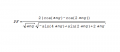
The result of that kind of calculation looks like this (see next post for correction):
PF=(2*(cos(ang)-cos(2*ang)))/(sqrt(ang)*sqrt(-sin(4*ang)+sin(2*ang)+2*ang))
where
'ang' is the phase angle, in this case it would be pi/2 for 90 degrees.
There is one catch here though. Although that would be the form or similar to the final form, I have to check it over again. I have a feeling the actual power factor 'may' be that divided by the square root of 2. I still have to check this, but the reason I think this is because the resulting areas, if aggregated in time, resemble a half-wave rectifier, which has a lower PF.
A couple things are interesting to think about there anyway. For one, the only parameter is the conduction angle 'ang'. That's because everything else drops out of the solutions, like the peak voltage, the average current, stuff like that, even the resistance. That would be typical in this kind of calculation for this kind of circuit. The general solution is:
PF=Pavg/Prms
and I am defining 'Prms' to be as before: Vrms*Irms.
Anyway, I would think the next step would be to use the resulting phase angle obtained from the calculated PF to calculate the required phase shift of the capacitor, even though the waveshape may not be to my liking.
We can look into the line resistance power dissipation improvement more also. There are also secondary factors which I may not want to get into like the skin effect, which would be worse with the introduction of higher harmonics, unless of course those harmonics actually decreased (haven't checked that either).
(See next post for correction of the attachment shown here)
Ok doing this over results in the correct solution, or at least it looks correct now. That's because of a few reasons for now:
1. The power factor 'PF' with the angle=pi/2 results in the same PF with a half wave rectifier (as expected).
2. The PF with angle = 0 results in the same PF as a full wave rectifier (also as expected).
3. The PF with the angle = pi results in a PF of zero (that means no output at all).
See attachment for the graph of PF as a function of the angle 'ang' with ang in radians. The graph below that shows PF as function of the angle in degrees, although the formula has to have the conversion of degrees to radians to replace 'ang' (ang=a*pi/180 then 'a' is the angle in degrees).
This also suggests that there can be a slight improvement of the power factor for a full wave bridge rectifier with a small conduction angle, although the average output voltage would drop slightly. The ideal angle looks like 20.345 degrees.
If anyone cares to simulate this to check it out that would be great I may not get to do that right away myself. Had to do a lot of running around today.
 Facebook
 Google
 GitHub
 Linkedin