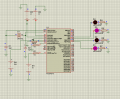
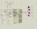
Comparator module initializing (pic16f877a)

Thread Starter

Wlillian

Joined Sep 8, 2021
26
Have you also got your interrupt routine? I see that you have switched interrupts on, but I can't see where you are handling it.

If you didn't want to use an interrupt you'll need to remove the lines of code that turn it on.
The output remained the same after removing the lines of the code that turn the interrupts on
 

Thread Starter

Wlillian

Joined Sep 8, 2021
26
I don't think it is doing the right thing because it CMCON.C1OUT hives only a low signal even if the input to C1 is greater than the reference voltage and CMCON.C1OUT gives a constant high signal even below the reference voltage.
Just so I'm not missing anything, could you please post you current code and schematic?
Alright.
 

Attachments

click_here

Joined Sep 22, 2020
548
I haven't used MikroC before, so I did a quick google and found this...

https://electrosome.com/analog-comparator-pic-microcontroller/

It is exactly what you want except using PortC.

I took a guess as to what I had to do to change it to PORTB - Try this...
Code:
void main()
{ 
  TRISB = 0; //Configure PORTB as output

  TRISA.RA0=1; // Configure as input pin for negative input of Comparator 1
  TRISA.RA1=1; // Configure as input pin for negative input of Comparator 2
  TRISA.RA2=1; // Configure as input pin for positive input of Comparator 1
  TRISA.RA3=1; // Configure as input pin for positive input of Comparator 2
  TRISA.RA4=0; // Configure as output pin for output of Comparator 1
  TRISA.RA5=0; // Configure as output pin for output of Comparator 2

  CMCON=0x05; // 'Two Common Reference Comparators with Outputs' Mode

  while(1)
  {
    PORTB.F6 = CMCON.C2OUT; // Assigning output of comparator 2 to RB0
    PORTB.F7 = CMCON.C1OUT; // Assigning output of comparator 2 to RB1
    Delay_ms(100);
  }
}
 

Thread Starter

Wlillian

Joined Sep 8, 2021
26

Attachments

djsfantasi

Joined Apr 11, 2010
9,156
Look back at post #8… When using these pins, your hardware schematic/build must include a pull-up resistor. None of your schematics show one.


Without the pull-up resistor, the pin output will always be low (or floating) and the LEDs won’t turn on.

Add pull-ups (or just one to test), and try again.
 

Thread Starter

Wlillian

Joined Sep 8, 2021
26
Look back at post #8… When using these pins, your hardware schematic/build must include a pull-up resistor. None of your schematics show one.

Without the pull-up resistor, the pin output will always be low (or floating) and the LEDs won’t turn on.

Add pull-ups (or just one to test), and try again.
I don't know but nothing has changed
 

click_here

Joined Sep 22, 2020
548
This...
Code:
CMCON=0*05;
CMCON.CM0=1;
Should be...
Code:
CMCON=0x05;
Because 0*05 = 0

Note that you are multiplying instead of doing a hex constant.
 

Thread Starter

Wlillian

Joined Sep 8, 2021
26
Before you played around with the code from that site, did it work? i.e. Did you test it? Because I see that you've added a lot.
Before editing according to that from the site, I got a high signal for C2 ana a low in the presence of CMCON.C1INV=1; and CMCON .C2INV=1; With the LEDs connected to RB7, RB6 and RB5 lighting.
When I changed CMCON.C1INV to CMCON.C1INV=0; LEDs connected to RB7 and RB5 were lighting.
When I removed these two initializations, only the LED connected to RB5 was lighting
 

Attachments

click_here

Joined Sep 22, 2020
548
10k is very high for an LED - 5V/10k = 0.5mA
I'd usually use 1k

Will someone please explain to me why this works without pull-up resistors
Why would you need pull up resistors on PORTB? PORTB is not an open collector output unless you set the output low and toggle the TRISB register.

LEDs connected to RB7 and RB5 were lighting.
Your code does not toggle RB5. [edit](in the code that you shared in post #31)[/edit]
 

Thread Starter

Wlillian

Joined Sep 8, 2021
26
Are the leds on pins B4/5 supposed to be on C4/5 - That would make more sense because then you would be looking at the output of the comparators.
10k is very high for an LED - 5V/10k = 0.5mA
I'd usually use 1k


Why would you need pull up resistors on PORTB? PORTB is not an open collector output unless you set the output low and toggle the TRISB register.


Your code does not toggle RB5. [edit](in the code that you shared in post #31)[/edit]
Even the outputs of the comparators are weird because C2 is constantly giving a high signal, C1 giving a constantly low signal that is when both inputs to the two comparators are higher than the external reference voltage (2.5V) but they don't give any output signal when theyr inputs are below the reference voltage. Am using mode 5
 
Top