Comparator module initializing (pic16f877a)

Thread Starter

Wlillian

Joined Sep 8, 2021
26
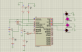
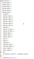
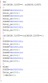
Hello, I need some help. I am using a pic16f877a with two hall effect sensors each connected to comparator. How can I write a code for the comparator module in mikroc pro for pic so that the comparator give outputs used to control the direction of rotation of a stepper motor. Any help will be highly appreciated.
 

click_here

Joined Sep 22, 2020
548
First step is by making a schematic.

Once you've done that go to the datasheet and read through that section and write down the behaviour that you want.

You may need to update your schematic based on any assumptions that you have made that are incorrect.

Next look at the registers that you'll need to set up to correspond with the behaviour, noting what registers need to be changed.

Now make the hardware.

After that is made, do a blinking led test to make sure that you can program the device correctly.

Now see if you can set up the comparator to control the output of the led with the input of a pot.

Now see if you can control the stepper motor to do a simple movement every second or so

Now that you have tested everything in isolation, start making a program that does what you need.
 

djsfantasi

Joined Apr 11, 2010
9,156
The previous post is totally a hardware perspective. You need to know how to solve the software issue as well.

Assign two pins as digital inputs. Connect the comparator outputs to them. They define four states.

Write code to perform the desired stepper rotation depending on each of the four states.

This assumes two things.

1) You’ve solved the issue of driving a stepper motor.

2) You know how to code.
 

Thread Starter

Wlillian

Joined Sep 8, 2021
26
First step is by making a schematic.

Once you've done that go to the datasheet and read through that section and write down the behaviour that you want.

You may need to update your schematic based on any assumptions that you have made that are incorrect.

Next look at the registers that you'll need to set up to correspond with the behaviour, noting what registers need to be changed.

Now make the hardware.

After that is made, do a blinking led test to make sure that you can program the device correctly.

Now see if you can set up the comparator to control the output of the led with the input of a pot.

Now see if you can control the stepper motor to do a simple movement every second or so

Now that you have tested everything in isolation, start making a program that does what you need.
Thank you , but am still having an issue.
I tried to do it using LEDs but the outputs of the portB are not as required even the RA4 pin indicates a low signal (blue) for almost microseconds and RA5 indicates a low signal .
 

Attachments

Thread Starter

Wlillian

Joined Sep 8, 2021
26
The previous post is totally a hardware perspective. You need to know how to solve the software issue as well.

Assign two pins as digital inputs. Connect the comparator outputs to them. They define four states.

Write code to perform the desired stepper rotation depending on each of the four states.

This assumes two things.

1) You’ve solved the issue of driving a stepper motor.

2) You know how to code.
 

Thread Starter

Wlillian

Joined Sep 8, 2021
26
Thank you for your help. But I tried to code but am having trouble with the outputs. Am used code 101 but the output at RA4 is a low signal which only appears for almost microseconds, that at RA5 being low which only turns to high when the voltage at both inputs of the comparators is above the reference voltage. Even the outputs at the portB are not as required.
 

Attachments

Thread Starter

Wlillian

Joined Sep 8, 2021
26
Thank you.
Another issue is that the output at portB remains the same as before and the I don't get a high signal for any of the comparators unless all inputs to these are greater than 2.5V which applied as the voltage reference.if one of the inputs is below 2.5V , then no signal will appear at that pin with this input. Could be using the wrong mode.
 

click_here

Joined Sep 22, 2020
548
Thank you.
Another issue is that the output at portB remains the same as before and the I don't get a high signal for any of the comparators unless all inputs to these are greater than 2.5V which applied as the voltage reference.if one of the inputs is below 2.5V , then no signal will appear at that pin with this input. Could be using the wrong mode.
According to your code, you have not set up portB at all

[edit]
Sorry I see that tucked away now
[/edit]
 
Last edited:

click_here

Joined Sep 22, 2020
548
Are you able to post your current code like this...


[code]
void main(void)
{
...
}
[/code]


It will look like this here...
Code:
void main(void)
{
   ...
}
That way we can see all of your code
 

Thread Starter

Wlillian

Joined Sep 8, 2021
26
Are you able to post your current code like this...


[code]
void main(void)
{
...
}
[/code]


It will look like this here...
Code:
void main(void)
{
   ...
}
That way we can see all of your code
The output is the same even when I change the port B assignments . The is below
C:
void main(){
TRISA.RA0=1;
TRISA.RA1=1;
TRISA.RA2=1;
TRISA.RA3=1;
TRISA.RA4=0;
TRISA.RA5=0;
TRISB=0;
ADCON1.RA0=1;
ADCON1.RA1=1;
ADCON1.RA2=1;
ADCON1.RA3=1;
ADCON1.RA4=0;
ADCON1.RA5=0;
CMCON=1;
CMCON.C1INV=1;
CMCON.C2INV=1;
CMCON.CM2=1;
CMCON.CM1=0;
CMCON.CM0=1;
PIE1=1;
PIE2=1;
INTCON=1;
INTCON.GIE=1;
INTCON.PEIE=1;
PIR2.CMIF=1;
PIE2.CMIE=1;
do{
if(CMCON.C1OUT==1&&CMCON.C2OUT==0)
{PORTB=0b11000000;
Delay_ms(500);
PORTB=0b01100000;
Delay_ms(500);
PORTB=0b00110000;
Delay_ms(500);
PORTB=0b10010000;
Delay_ms(500);
}
if(CMCON.C1OUT==0&&CMCON.C2OUT==1)
{
PORTB=0b10010000;
Delay_ms(500);
PORTB=0b00110000;
Delay_ms(500);
PORTB=0b01100000;
Delay_ms(500);
PORTB=0b11000000;
Delay_ms(500);
}
else{
PORTB=0b00000000;
Delay_ms(500);
Mod edit: code tags - JohnInTX
 
Last edited by a moderator:

click_here

Joined Sep 22, 2020
548
Well... not writing to the correct pin would do it, but see if this works: Comment out the body of the loop and try this...
Code:
do
{
    if(CMCON.C1OUT == 1)
    {
        PORTB |= 0b10000000;
    }
    else
        PORTB &= 0b01111111;
    }

    if(CMCON.C2OUT == 1)
    {
        PORTB |= 0b01000000;
    }
    else
        PORTB &= 0b10111111;
    }
}
while(1);
You need to see if CMCON.CxOUT is doing what you expect without anything else.
 

Thread Starter

Wlillian

Joined Sep 8, 2021
26
Well... not writing to the correct pin would do it, but see if this works: Comment out the body of the loop and try this...
Code:
do
{
    if(CMCON.C1OUT == 1)
    {
        PORTB |= 0b10000000;
    }
    else
        PORTB &= 0b01111111;
    }

    if(CMCON.C2OUT == 1)
    {
        PORTB |= 0b01000000;
    }
    else
        PORTB &= 0b10111111;
    }
}
while(1);
You need to see if CMCON.CxOUT is doing what you expect without anything else.
I don't think it is doing the right thing because it CMCON.C1OUT hives only a low signal even if the input to C1 is greater than the reference voltage and CMCON.C1OUT gives a constant high signal even below the reference voltage.
 

click_here

Joined Sep 22, 2020
548
Have you also got your interrupt routine? I see that you have switched interrupts on, but I can't see where you are handling it.

If you didn't want to use an interrupt you'll need to remove the lines of code that turn it on.
 
Top