Communication Protocol

Thread Starter

sidd342

Joined Oct 9, 2023
32
Hi there,

I'm working on a project using a microcontroller that has to read a UART communication some interrupts.
On the basis of what I'm aware, the UART communication protocol reads one byte of data at a time in addition to stop and start bits.
However in the communication protocol for me, I only get one start and stop bit per frame structure.

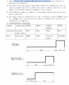
The frame structure is shown below

One frame of data is transmitted at a time, including a total of 97 bits, a start bit, 12*8 data bits, and the line idle state is required to be low after the
transmission is completed.

Can someone help me understand how I can integrate this frame structure in a UART based protocol?
Thanks
Siddharth
 

nsaspook

Joined Aug 27, 2009
16,251
You mean something like this: start -> byte1-byte2-byte3-byte4-byte5-byte6-byte7-byte8-stop
What exactly is this protocol for? How about some detail on the device and why it needs to use this non-standard encoding.
 

Papabravo

Joined Feb 24, 2006
22,058
I think you have some obstacles to understanding. The reason for having a 10 or 11 bit frame for asynchronous communication is that there is no required clock signal that needs to be the same at BOTH the receiver and transmitter. If you want more data in a single frame there is CAN (Controller Area Network). If you want larger frames there are any number of synchronous protocols that involve passing clock signal or doing clock recovery from the data.

It is trivially easy to layer a higher-level protocol on the exchange of single bytes in a hardware UART. On top of that a UART is full duplex and can support simultaneous traffic in both directions which is not allowed in most synchronous protocols.
 

Thread Starter

sidd342

Joined Oct 9, 2023
32
You mean something like this: start -> byte1-byte2-byte3-byte4-byte5-byte6-byte7-byte8-stop
What exactly is this protocol for? How about some detail on the device and why it needs to use this non-standard encoding.
Yes that is exactly what I mean. The protocol referred here is the SIF protocol. I'm building a display console for an electric vehicle and this is how I'm receiving the data from the device.

I have also attached some reference link for the same.

https://python.quectel.com/doc/Application_guide/en/hardware/peripheral-interfaces/GPIO_sif.html#:~:text=SIF protocol is simple and,from the 1-Wire protocol.

This is exactly how I'm receiving the data.
Also attached the screenshot of the datasheet.
 

Attachments

Last edited:

Thread Starter

sidd342

Joined Oct 9, 2023
32
I think you have some obstacles to understanding. The reason for having a 10 or 11 bit frame for asynchronous communication is that there is no required clock signal that needs to be the same at BOTH the receiver and transmitter. If you want more data in a single frame there is CAN (Controller Area Network). If you want larger frames there are any number of synchronous protocols that involve passing clock signal or doing clock recovery from the data.

It is trivially easy to layer a higher-level protocol on the exchange of single bytes in a hardware UART. On top of that a UART is full duplex and can support simultaneous traffic in both directions which is not allowed in most synchronous protocols.

I understand what you are explaining. However the issue is that the controller for which I'm reading the data, send out data adopting an SIF protocol. The same protocol has the requirements I mentioned.

https://python.quectel.com/doc/Appl...otocol is simple and,from the 1-Wire protocol.
 

nsaspook

Joined Aug 27, 2009
16,251
Yes that is exactly what I mean. The protocol referred here is the SIF protocol. I'm building a display console for an electric vehicle and this is how I'm receiving the data from the device.

I have also attached some reference link for the same.

https://python.quectel.com/doc/Application_guide/en/hardware/peripheral-interfaces/GPIO_sif.html#:~:text=SIF protocol is simple and,from the 1-Wire protocol.

This is exactly how I'm receiving the data.
Also attached the screenshot of the datasheet.
No, you can't do that with a regular UART module. International standard SIF communication protocol, no it's not, but you can easily bit-bang a 1-wire protocol to handle that slow data protocol. It seems IMO the protocol is designed to lock you into a specific programming system from the company by using something non-standard on most controllers.
 

Thread Starter

sidd342

Joined Oct 9, 2023
32
No, you can't do that with a regular UART module. International standard SIF communication protocol, no it's not, but you can easily bit-bang a 1-wire protocol to handle that slow data protocol. It seems IMO the protocol is designed to lock you into a specific programming system from the company by using something non-standard on most controllers.
So the best way around this would be bit banging?
A problem with bit banging I can think of is very frequent timer interrupts (for a good value, I need to have an interrupt every 250uS). This interrupt would constraint my ability to write data in EEPROM or other processes.
But I believe that the only way to leverage this is protocol is using bit banging. Best we can do is instead of reading this data every time we get it, we can skip some data and do other functions meanwhile.
The microcontroller I'm using, the same as that used on the current device used to read this data is CMS79F1361. The input from this wire is connected to RB6.
Also attached the datasheet below for the microcontroller.
 

Attachments

Last edited:

Papabravo

Joined Feb 24, 2006
22,058
Looks like the best approach might be to consider an FPGA with a SIF engine and a FIFO memory. This would be easy if there is a Verilog or VHDL SIF engine in the public domain. If this is your first FPGA project, it might be a heavy lift to make a SIF engine from scratch.

OTOH, if you uP has an input capture module, I can see how you might use that as a receiver. I did this one upon a time with an IR remote receiver. works pretty well and definitely unloads the processor. The output compare module would work for a transmitter.
 

Ian0

Joined Aug 7, 2020
13,097
What about using the USART in sync mode?

V1.1.2 CMS79F13x 97 / 143www.mcu.com.cn 14.5 USARTx Synchronous Mode (pdf page 102)
https://www.mcu.com.cn/uploads/img1/tupian/手册下载/CMS79F13x User Manual_V1.1.2.pdf
Synchronous mode requires a clock signal, which he doesn't have.
This looks like the same protocol as a WS2812 LED.
Easy to output from an SPI interface but trickier to input.
Set the device to interrupt on a falling edge. In the interrupt routine, delay 750us then read the pin. That is your data.
Shift it into the output register one bit at a time.
Not too tricky to implement in hardware either, using a falling-edge triggered 750us monostable then a shift register clocked on the trailing edge of the monostable output pulse.
 

Thread Starter

sidd342

Joined Oct 9, 2023
32
Synchronous mode requires a clock signal, which he doesn't have.
This looks like the same protocol as a WS2812 LED.
Easy to output from an SPI interface but trickier to input.
Set the device to interrupt on a falling edge. In the interrupt routine, delay 750us then read the pin. That is your data.
Shift it into the output register one bit at a time.
Not too tricky to implement in hardware either, using a falling-edge triggered 750us monostable then a shift register clocked on the trailing edge of the monostable output pulse.
Yes indeed, the protocol seems to be similar to that of WS2812 LED, with an additional advantage that the time delay is not in the range of micro seconds but mili seconds.
The approach you mentioned seems easy enough to implement. I will try implementing using a software version first and see how it goes from there.
Thanks for the help
Siddharth
 

Ian0

Joined Aug 7, 2020
13,097
Makes me wonder why they just didn’t simply use Manchester coding, because some processors have UARTs which can do that.
 

John P

Joined Oct 14, 2008
2,051
So the best way around this would be bit banging?
A problem with bit banging I can think of is very frequent timer interrupts (for a good value, I need to have an interrupt every 250uS). This interrupt would constraint my ability to write data in EEPROM or other processes.
...
For most processors, a 4KHz interrupt rate is nothing much, unless you really need to do a lot of stuff each time, which doesn't seem to be the case here. A possible alternative would be to interrupt on an edge in the incoming signal, and use a timer to tell you whether you're seeing a long pulse or a short one, or a sync signal.
 

Ian0

Joined Aug 7, 2020
13,097
If you trigger a monostable (74HC123) on the falling edge of the data signal, and give it a 750uS timeout, you can connect the output to the clock of the SPI module. The incoming datastream can go to MISO. You can set the SPI module to sample MISO on the falling edge of the clock, so you should be able to read the data with an SPI peripheral and a monostable.
 

nsaspook

Joined Aug 27, 2009
16,251
If you trigger a monostable (74HC123) on the falling edge of the data signal, and give it a 750uS timeout, you can connect the output to the clock of the SPI module. The incoming datastream can go to MISO. You can set the SPI module to sample MISO on the falling edge of the clock, so you should be able to read the data with an SPI peripheral and a monostable.
You could likely use a controller with a CLB for that decoding frontend.
https://www.ti.com/video/series/C2000-configurable-logic-block.html
https://www.microchip.com/en-us/product/PIC16F13145

I've used controller logic modules for SPI to WS2812 generation so the reverse should also be possible.
https://mplab-discover.microchip.co...spi-ws2812-mplab-mcc/1.1.0?view=about&dsl=CLB

https://forum.allaboutcircuits.com/...s-with-controlling-an-led.199346/post-1893329
https://github.com/nsaspook/q84_wsled

This demo is based on the PIC18F47Q84 Curiosity HPC platform which illustrates how a pulse-width modulated WS2812 signal can be decoded using the new Universal Timer (UTMR) module along with other PIC® Core Independent Peripherals (CIPs) like SPI, CLC, and CCP. This demo also shows an example of generating WS2812 signal using the new 16-bit PWM module, SPI, and CLC.
 
Last edited:

John P

Joined Oct 14, 2008
2,051
Another way to do it would be to feed the incoming signal into a UART's RX pin, having set the baud rate to something like 8K bits per second. Then a incoming 1 (0.5msec low) would give you 3 low data bits, 0x11111000, and an incoming 0 (1.0msec low) would give you 7 low data bits, 0x1000000. (Remembering that in each case, there's a start bit ahead of the actual data.) And the long sync pulse would cause a framing error, which you can test for. So you'd get an incoming "character" for every incoming bit, and you could reassemble the bit stream from that.
 
Top