Colpitts oscillator not working as expected

Thread Starter

Robin Mitchell

Joined Oct 25, 2009
819
Hi all,

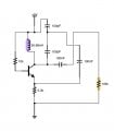
I have designed a simple Colpitts oscillator as shown below:

In LTSpice it works great! I have built this in real life with all values the same. The only difference is that the transistor used is a BC548 instead of what is shown (This is because I know that the 2N3904 and the BC548 are interchangable).

When I power the circuit I DO get an oscillation however it is very small in amplitude (less than 1vPP) and there is a large DC offset (about half the supply typically).

What is going on?
It should be noted that the circuit is built on breadboard so will parasitic capacitance affect anything?

All the best,
Robin
 

bertus

Joined Apr 5, 2008
22,884
Hello,

The coil L1 is extremely small, try a value of about 100 X larger eq. 1 μH.
The capacitors C2 and C3 can be reduced to about 200 pF.

Also a breadboard will have parasitic capacitance.

Bertus
 

GopherT

Joined Nov 23, 2012
8,009
What values did you use to get 100MHz?
And any pictures?

Many thanks :) !
I think it was 1 nF capacitors and 5nH coil. Coil was made by wrapping standard 22 gauge insulated solid hookup wire around a pencil 6 or 7 times (maybe it was 9 times?). There are calculators on line. I was able to pick up the silence on an fm radio. Then stretch the coil a bit (just spring-like, not deforming permanently) so you can hear the fm receiver catch and lose the signal. The signal was quite strong - up to 2x supply voltage.
 

GopherT

Joined Nov 23, 2012
8,009
100nf tank capacitors and 50nF inductor

Also, the load on the output must be very low or you will lose your signal.

My output was the 10M ohm cap (I need to measure voltage across a component on my ipad simulator - no meter available).

The output across the 10M resistor is 6.5 v peak to peak. 100 MHz.

Also, you should expect 20 to 30 pF across each tank cap from board capacitance so use 68 or 82pF caps for prototyping.

Coil could be 5 turns, 0.25" about 0.7" long.
Calculate your own coil here. This site will post as 5.00E-002 microhenries
http://www.66pacific.com/calculators/coil_calc.aspx


Cheers


Attachments

Last edited:

Thread Starter

Robin Mitchell

Joined Oct 25, 2009
819
Ok so I built this too. Nothing.

I have used the BC548 as the active component (and tried multiple devices), and I am using a 20MHz oscilloscope (which is analoge).
I used all the values you suggested but for some reason there is no oscillation :(
 
Last edited:

GopherT

Joined Nov 23, 2012
8,009
image.jpg Increase the size of the components in the tank.
The must stay somewhat "balanced" (as you go up in size). Not linear but make sure your simulator sows a signal just above your supply voltage. Also, not all simulators will work with self-oscillating circuits without an initials perturbation (enter a starting value).

Here is a simulation of a 1MHz oscillator. Note that the slower you go, the more difficult it is to keep it going. Use the fattest wire (lowest resistance) coils possible and lowest ESR capacitors possible since the simulators do not have resistance in the ideal components.
 
Top