Facebook
 Google
 GitHub
 Linkedin
Hello there,
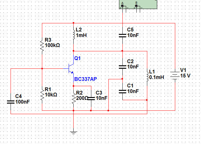
I'm gonna try to build a simple Theremin, pitch only with only two oscillators and amp. Well I've got some schematic and information about LC oscillators at school, the problem is that only theoreticaly, I don't have a clue about practical stuff, what values should I use, which oscillator is better or just anything.
So my question is which design would be the best (good sine wave, stable frequency) and if you could help me also with values.
I definitelly need frequency about 400kHz, voltage supply about 15V, capacitors in the tank circuit in pF and it would be good to have one 'end' of the tank circuit connected to ground so I could change it's capacity by my body (hand) between a antenna and the ground.
Actually frequency is only thing I can get from C and L values and as I've tried to simulate one schematic which I found on the internet, with frequency which suits my requirements, but it had nF capacitances so small change by hand. So I've tried to change the values to pF and at the same time used 1000x bigger coil, but still it stopped oscillation. Sorry if I something wrote wrong, but I have just some basics from school.
I'd really appreciate someone's help, thanks a lot
Monow.