coil noise in boost converter

Thread Starter

mohammadhossein ajorloo

Joined Aug 27, 2016
17
hi
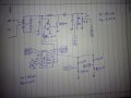
i am desigening a boost converter (LED driver) With the following characteristics:
vin: 12-24volt dc and ac
vout: 40-60volt dc
iout: .3 Amper
f: 200Khz
but my coil have alot of noise.
what should i do???
 

Thread Starter

mohammadhossein ajorloo

Joined Aug 27, 2016
17
Give us more information so we can understand what is happening.

Describe "alot of noise".
What are you using to measure it, what type of probe, where are you measuring it, what is its voltage, what does it look like?
Why is this a problem?
I am not measuring it. it is audible noise and a can hear it and It is a big problem.
My switching frequency is 200Khz and i dont now why it has audible nose?
 

ebp

Joined Feb 8, 2018
2,332
What does "vin: 12-24volt dc and ac" mean?

If the noise is low frequency, that is at the frequency of ripple on the input supply, then it is likely due to modulation of the the pulse width as it compensates for the input ripple. Better input filtering or a better inductor is required.

If the noise is high frequency, it is most likely due to instability in the circuit due to incorrect frequency compensation or electrical noise which may be due to inappropriate components for poor layout.

If low frequency PWM is being used to dim the LEDs then that is very likely the cause of the noise and nothing can be done other than finding a better inductor.
 

MisterBill2

Joined Jan 23, 2018
18,584
Transformers and inductiors with loose turns will indeed vibrate if the current is varying, but after the insulation wears through and they short circuit the noise will diminish. So to stop the sound from the coil the normal approach is to embed it in varnish. Some folks use tar, which also works but it is very nasty to deal with.
 

Thread Starter

mohammadhossein ajorloo

Joined Aug 27, 2016
17
What does "vin: 12-24volt dc and ac" mean?

If the noise is low frequency, that is at the frequency of ripple on the input supply, then it is likely due to modulation of the the pulse width as it compensates for the input ripple. Better input filtering or a better inductor is required.

If the noise is high frequency, it is most likely due to instability in the circuit due to incorrect frequency compensation or electrical noise which may be due to inappropriate components for poor layout.

If low frequency PWM is being used to dim the LEDs then that is very likely the cause of the noise and nothing can be done other than finding a better inductor.
my circuit should work with 12volt ac,12volt dc, 24volt ac and 24volt dc for that i am using a Bridge Rectifiers and a capacitor in the input if the circuit.
the input capacitor is 680uf and i am change it many time.
my switching Voltage Regulators is Tl494.
iam change the inductor many time and when i use a coil with much more inductance the noise reduce but i use 200Khz frequency to use a small coil.
 

ebp

Joined Feb 8, 2018
2,332
What frequency is the noise from the inductor? 100 or 120 Hz or something much higher?

I think it is very likely that your circuit is unstable, possibly even "squegging" (you can find what that means on the web).
Is the circuit built on a printed circuit board or some kind of breadboard? Solderless breadboards are especially bad for switching power supplies.
 

Thread Starter

mohammadhossein ajorloo

Joined Aug 27, 2016
17
What frequency is the noise from the inductor? 100 or 120 Hz or something much higher?

I think it is very likely that your circuit is unstable, possibly even "squegging" (you can find what that means on the web).
Is the circuit built on a printed circuit board or some kind of breadboard? Solderless breadboards are especially bad for switching power supplies.
my circuit is on a pcb and in two modes i dont have audible noise:
1. when i'm not control current and my input voltage is 24volt ac and my out put is 60volt with 500ma
instead if 300ma (Is it possible that the feedback make noise, my feed back is a 1ohm resistant).
2. when my input is 12volt dc and i use a 1500Pf cap Parallel with the coil.
 

MisterBill2

Joined Jan 23, 2018
18,584
There are often a number of other frequencies involved aside from the intended frequency. And since every regulated supply has some sort of feedback, that may be a source of oscillation as well. Given that we have no circuit to look at, my suggestion is still to encapsulate the coil so that any vibration is impossible.
 

ian field

Joined Oct 27, 2012
6,536
There are often a number of other frequencies involved aside from the intended frequency. And since every regulated supply has some sort of feedback, that may be a source of oscillation as well. Given that we have no circuit to look at, my suggestion is still to encapsulate the coil so that any vibration is impossible.
Last time I saw damping failure on a TL431 - the PSU blotted out FM reception for a few hundred yard radius.
 

DickCappels

Joined Aug 21, 2008
10,187
In addition to checking your circuit for loop stability, consider some other possible solutions:

1) Rewind, keeping a lot of tension on the wires.

2A) Pot the transformer in hard potting compound or,

2B) Dip teh transformer in a varnish like Varathane. It might need several dipping/drying cycles,, or

3) Buy one of these. (just kidding)
upload_2019-1-3_18-37-3.png
 

MisterBill2

Joined Jan 23, 2018
18,584
DC is suggesting the same as I did quite a while back, except that rewinding tighter will change the inductance a bit and that will have some effect. The varnish treatment should work, potting in hard compound is difficult to get 100% fill, so I do not recommend it.
 
Top