Facebook
 Google
 GitHub
 Linkedin
Hello to everyone, if you check my profile you will see that I am an auto mechanic, I can help you with your car - no problem but this electronics stuff is a brain killer. I can troubleshoot them but have trouble building them. Some of the stuff you guys talk about here is making me sweat!
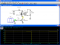
What I would like to build is a coil driver. I want to test a coil off and away from the vehicle. The coils generally have a 1 ohm primary resitance and about 5-7kΩ secondary. they are capable of producing as much as 100κv but really need averge 10κv and max of about 25κv. different vehicles vary slightly but usually I can test the coil output with a special spark tester with a load of estimated value of 25κv. The problem is that I have to crank over the engine and allow the vehicles electronic system to activate the coil. Some vehicles you have to remove the intake manifold to get to the coils and not a good time to be cranking engine over.
I have a 2n3055 transistor to fire the coil, a pulse width driver used to pulse fuel injectors to drive transitor base and a condensor to place at positive pole of primary windings to ground (all ignition systems use a condensor at the coil) don't know why they just do. I think it's to prevent arcing from spikes.
I'm posting my idea to gather insite and any thoughts I should consider before I build.
I do have one direct question though. Transistor states
Vebo = 7v what does that represent?