Coffee Machine Delonghi EC7.1 - Electrical parts

Wolframore

Joined Jan 21, 2019
2,610
NO! a thermal fuse is a safety device that cuts off the power and can not be reset. So it is not part of any normal operation.
I believe the switches fail open.

this is why I believe so

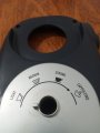
this machines has a steam setting at the extreme left
86DD61A6-78C2-4088-87FA-FF5E4C21EE0F.jpeg

this wiring diagram shows a switch that bypasses the low thermostat
7A764282-06AA-4BBC-8B0B-780D1CABA631.jpeg
 

Thread Starter

Freeman Dom

Joined Dec 2, 2021
44
Really, if the temperature of the thermal fuse is too close to the working temperature then it will fail open and that will be quite inconvenient. 227C is not hot enough to start fires but well beyond normal operation. AND the thermal fuses often open below their claimed set-point.
So, 227 C is adequate for this thermal circuit, that's logic.
But still wrong diagram, the Thermal fuse must be between thermoStat and heater, there is no other possible condition.
 

MisterBill2

Joined Jan 23, 2018
18,595
I have had both switches and relays fail in the closed contacts mode, usually with the contacts welded. Switches fail open due to mechanical wear, they fail closed due to welded contacts, mostly, but also due to mechanical failures. AND I have experienced a coffee maker where the thermostat failed closed, and only the safety fuse prevented it from burning up and starting a fire.
 

Thread Starter

Freeman Dom

Joined Dec 2, 2021
44
I have had both switches and relays fail in the closed contacts mode, usually with the contacts welded. Switches fail open due to mechanical wear, they fail closed due to welded contacts, mostly, but also due to mechanical failures. AND I have experienced a coffee maker where the thermostat failed closed, and only the safety fuse prevented it from burning up and starting a fire.
It looks a little bit strange about starting fire from coffe maker machine, I gusse it's just about pressuer issue not fire issue. In this Ec7 I find a mechanical pressureSwitch in the steam boiler plastic cap.
Here is the tow Closed/Open photos, I'm rethinking that ThermoStat is mainly for Steam pressure issue due to the temperature value.
 

Attachments

MisterBill2

Joined Jan 23, 2018
18,595
A coffee machine has a medium powered heater, several hundred watts, mounted into a plastic outer case. If the thermostat stuck closed, (on) and all of the water was evaporated, it would continue to heat, getting hotter and hotter, and at some point it might get hot enough to ignite whatever material is in contact with it, as the heater assembly continues to get hotter. When the coffee maker of mine failed, stuck ON, it was on a polyethylene plastic table that might have ignited eventually.
 

Thread Starter

Freeman Dom

Joined Dec 2, 2021
44
A coffee machine has a medium powered heater, several hundred watts, mounted into a plastic outer case. If the thermostat stuck closed, (on) and all of the water was evaporated, it would continue to heat, getting hotter and hotter, and at some point it might get hot enough to ignite whatever material is in contact with it, as the heater assembly continues to get hotter. When the coffee maker of mine failed, stuck ON, it was on a polyethylene plastic table that might have ignited eventually.
I'm starting to belive that a ThermoStat is a vivacious element in thermal circuits, or maybe it's the most important element.
I attached here the very first copy of the wiring diagram for the Ec7, any remarks will be greatly appreciated.
 

Attachments

MisterBill2

Joined Jan 23, 2018
18,595
I'm starting to belive that a ThermoStat is a vivacious element in thermal circuits, or maybe it's the most important element.
I attached here the very first copy of the wiring diagram for the Ec7, any remarks will be greatly appreciated.
The circuit is almost correct, EXCEPT that the ground symbol and the green wire should not be connected with the neutral(blue wire)section. And the symbols are not what is commonly used.
The "green wire ground"is exclusively included to assure that the portions of the device that are not intended to be part of the circuit are at "ground" potential.
The whole "green wire" system is intended to prevent an electrical shock hazard. Thus it is, by the way,a LARGE additional expense for protection against a hazard that is usually not present, because most electrical devices are not defective. I am aware that this remark will launch a firestorm of "But What if" responses, but that is the reality.
The green wire system is not intended to carry operating currents at all, it's only purpose is prevention of shock hazard when there is a failure.
 

Wolframore

Joined Jan 21, 2019
2,610
this Is absolutely correct and when you want CE and UL cert, it will be necessary to add… the Green is only on the “chassis” or the metal body of the pump. It does not provide a return
 

MisterBill2

Joined Jan 23, 2018
18,595
In any useful circuit there are three required elements: The source of power, the useful load, and the control means. This circuit also contains other components, the indicator light (another load), and the safety shutoff (another control).
 

Thread Starter

Freeman Dom

Joined Dec 2, 2021
44
I am so Thankfull for your Guidance.:)
Ok, here, I updated the green wire connection and add the sub-circuit Switch in the diagram circuit for better current flow understanding.
just i want to understand, when there is a some Failure, any path will the current take from the chassis to the ground ?
and what about the symbols commonly used in this type of circuit ? there is many propositions in google.
If I want have CE and UL certs for this circuit diagram, what i should add ?
Now things become more clearly, I think i have to write the math equation for a Cappuccino.
 

Attachments

MisterBill2

Joined Jan 23, 2018
18,595
I am so Thankfull for your Guidance.:)
Ok, here, I updated the green wire connection and add the sub-circuit Switch in the diagram circuit for better current flow understanding.
just i want to understand, when there is a some Failure, any path will the current take from the chassis to the ground ?
and what about the symbols commonly used in this type of circuit ? there is many propositions in google.
If I want have CE and UL certs for this circuit diagram, what i should add ?
Now things become more clearly, I think i have to write the math equation for a Cappuccino.
It looks right, but I think that the heater is a lot more that 222 milliwatts. Where does tat number come from??
 

MisterBill2

Joined Jan 23, 2018
18,595
The heater powered 800 Watts per hours, so 800/3600 = 0.222 W per second, then x 1000 = 222 mW per second.
NO!! The heater draws 800 watts constantly while it is powered. It may consume 222 miliwatthours per second, but that number is irrelevant to the current flowing through the heater and associated wiring. The 222 mW number has no value in the description of the appliance, nor is it part of the way heater power draw is noted.
 

Thread Starter

Freeman Dom

Joined Dec 2, 2021
44
NO!! The heater draws 800 watts constantly while it is powered. It may consume 222 miliwatthours per second, but that number is irrelevant to the current flowing through the heater and associated wiring. The 222 mW number has no value in the description of the appliance, nor is it part of the way heater power draw is noted.
I think I get confused between the heater Power rating and the energy consuming,
Can I put 800 joule per second as specefic heater value in the circuit ? or it must be just 800 Watts ?
 
Top