The circuit shown in post #20 is interesting but the way the connections to the red and green lights are shown does not help much with seeing how to connect to the switch on the actual machine .
OK, a number of things have become clear after examining the photos again in a magnified mode. There is no second heater element, there is only the main thermostat that is adjustable and an over-temperature thermal fuse in that section of plastic tube that has a white wire on one end and the black wire on the other end. There were no "modifications" made, the crimp splices are used to connect the internal wires to the line cord.
Note that the power switch has three terminals and if the TS did not very carefully note which wires went to which terminals there will be a big problem. That is because the switch is a lighted switch and so both sides of the mains power are connected to the switch, and if the connections are incorrect then the switch will close directly across the mains power, which will damage the switch and make it unusable. Note also that in none of the vies showing the wires do we have enough information to provide valid advice as to the correct connections. And the three switch connections do not show in that diagram.
Yes there is onlye one ThermoStat, but why it must be Adjustable ?
Yes there is no wire sections modifications, but it looks there is, maybe it will be more clear if i understand the basic rules of drawing the wiring diagram, and as you have noticed the cabling of the power switch is very imortant in the circuit, I tghout it's secondary issue.
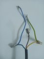
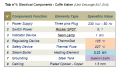
Here the 10 Male Connectors of the wiring diagram.
Yes there is only one ThermoStat, but why it must be Adjustable ?
Yes there is no wire sections modifications, but it looks there is, maybe it will be more clear if i understand the basic rules of drawing the wiring diagram, and as you have noticed the cabling of the power switch is very imortant in the circuit, I tghout it's secondary issue.
Here the 10 Male Connectors of the wiring diagram.
My advice, which is a little late, is to take pictures and document better before disassembly. If you do some searching you may be able to find a wiring diagram. It’s a simple circuit.
I do agree with your advice, just things was not as clearly as now, and yes I'm doing some searching but in the same time
I prefer to etablish the wiring diagram than I find it, then maybe I can Test it with eventual free wiring diagram software ? I will see if I can select one and use it in this issue.
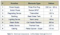
Thanx for the EC155 diagram, Here is the update table for the circuit elements and a similar figure for their position in the futuer diagram, if there is no technical obstacle.
OK, and the photos are good. I see the switch, on the other side, not shown in the photo, there may be information about the connections that will tell which is the switch common (to the thermostat), the brown line input, and the mains common connection for the indicator light. On the heater section are both heater connections and the double connector for the yellow and green ground wires.
# 26:
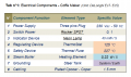
I re-labeled it to just "Heater", and I updated the table and diagram with the remarks 2 and 3.
the remark 4, does it not done inside the switch element ? that what SPST means ? I think that but i'm not sure.
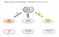
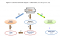
I was thinking about the current path in the circuit, for making the wiring diagram but there is some not clear issues, so i change the horizontal diagram to a vertical sheamtic one, it looks aisier to me for imaginig the current path, or at least understand it logically, here the schematic diagram and any help will be appreciated.
# 2 7:
In the post #22, in the switch photo there is 3 number 1 2 3, maybe that you meant ?
the brown line is the main connection for the lamp or for the heater ? Btw, how much power (w) should be red neon lamp ? about 40 w ?
I changed the " Lighting advice" with Indicator advice as you said, we dont need light in this system unless for evantual danger indication, and i think it's the hight pressure inside the steam boiler in this system.
Ok, I meant ONE WATT minute (1 Watt / Coffee), I updated it 40 mW/s untill I find the exact indicator power value,
in the other side i still dont understand why there is a huge difference between ThermoStat (125°C ) and the Thermal Fuse (227 °C ) values, i dont know if I should understand this for better wiring diagram analysis, or it's not so important.
Ok, ThermoStat and ThermoSwitch are both in series with power now.
Just wanted to know what about if we remplace the 227 C Fuse by 150 C Fuse for example, will that create some problems electrically ?
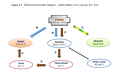
Maybe there is 1 light, Written in the power switch :
side A : 15 (13) A 250V - T85
DRD - 112 1E4
Side B : 12 A 125 VAC
1 2 3
If there is 1 light, maybe the diagram will be like this attached photo, and I think I have to decompose the switch power to different elements, for better understanding, it's looks like electric rond-Point.
Ok, ThermoStat and ThermoSwitch are both in series with power now.
Just wanted to know what about if we remplace the 227 C Fuse by 150 C Fuse for example, will that create some problems electrically ?
Really, if the temperature of the thermal fuse is too close to the working temperature then it will fail open and that will be quite inconvenient. 227C is not hot enough to start fires but well beyond normal operation. AND the thermal fuses often open below their claimed set-point.
 Facebook
 Google
 GitHub
 Linkedin