Clipping Class AB Amplifier output

Thread Starter

Whiskey-Kiss

Joined Dec 22, 2017
7
Hello,

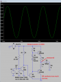
I have a 16V single supply amplifier design, the output of which is clipping at +/- around 1.5V.

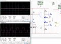
When I disconnect the output stage, and view the waveform at the emitter of Q11, there is a clear waveform of about 5V peak-to-peak, with just a bit of expected non linear distortion, but as soon as I load it with the output stage I get the red waveform visible on the lower oscilloscope screen, and the output from emitter follower Q11 is clipped at -2V, visible as the blue waveform on the upper osc screen.

I have measured the DC bias around the circuit and it is consistently around 8V. There is a clear signal of about 20mV going into the base of common emitter Q9, which is biased at around 2.5V, and I have a quiescent current of around 1mA through the diodes.

I was wondering if anyone might be able to tell me why this is happening? What am I doing wrong in the output stage?

If you need any more info please let me know.

Thanks for looking!
 

Attachments

crutschow

Joined Mar 14, 2008
34,432
Resistor value R8, R10, and R18 are too high .
There is not enough base current available for Q5 and Q7 to drive an 8 ohm load.
How did you calculate those values?

One solution is to use a Darlington or Sziklai pairs for the output stage to increase the current gain and reduce the drive requirements.
(The Sziklai pair has the advantage of having only a 1 diode base-emitter voltage-drop whereas the Darlington has 2, thus allowing the output to go closer to the supply voltage).
 

Thread Starter

Whiskey-Kiss

Joined Dec 22, 2017
7
Resistor value R8, R10, and R18 are too high .
There is not enough base current available for Q5 and Q7 to drive an 8 ohm load.
How did you calculate those values?

One solution is to use a Darlington or Sziklai pairs for the output stage to increase the current gain and reduce the drive requirements.
(The Sziklai pair has the advantage of having only a 1 diode base-emitter voltage-drop whereas the Darlington has 2, thus allowing the output to go closer to the supply voltage).
Ok, I'll look into using a couple of Sziklai pairs, though I have no experience using them! How much current should be available at the bases? Is it dependant on the specs of the transistors? As you can probably tell I'm not very experienced or practiced in amp design!

Also, I thought that I wanted a high input resistance from the emitter follower Q11 which is why I set its emitter resistor fairly high. Is this not the case then? Should it perhaps be 800 ohms, ie. 10 times greater than the CE amp's output resistance, once it has been multiplied by hfe?

Thanks a lot for your help
 

Thread Starter

Whiskey-Kiss

Joined Dec 22, 2017
7
Sorry, I wasn't thinking.

I want a 1W output stage through an 8 ohm load, so it needs 353mA. Assuming a beta of 50 (using my current setup) that means I need around 7mA available at the base of the transistors. As the push-pull pair aren't working at the same time, will 7 or 8 mA be enough, or will I need to double that?

I'm still not sure what to do about R18 though..
 

Audioguru

Joined Dec 20, 2007
11,248
Your Q11 driver transistor is driving the diodes, not the output transistors.
Q11 should replace your R10 as a common emitter type, then your R10 and R18 are not needed. For Q5 to turn on with its emitter at 3V its collector current is 1.375A and its base current is at least 13.8mA. Then your R8 must be (3V - 0.7V)/13.8mA= 167 ohms. The little transistors will explode if they try to conduct 1.375A.

The amplifier has no negative feedback so it will have awful distortion.

I simulated an amplifier with less supply voltage and less power. The current in the driver transistor is very high so the distortion is quite low. The voltage gain is very high, my simulation has an input of only 5.2mV peak. If the driver current is reduced then the distortion will be very high unless bootstrapping and negative feedback are added.
 

Attachments

Thread Starter

Whiskey-Kiss

Joined Dec 22, 2017
7
Your Q11 driver transistor is driving the diodes, not the output transistors.
Q11 should replace your R10 as a common emitter type, then your R10 and R18 are not needed. For Q5 to turn on with its emitter at 3V its collector current is 1.375A and its base current is at least 13.8mA. Then your R8 must be (3V - 0.7V)/13.8mA= 167 ohms. The little transistors will explode if they try to conduct 1.375A.

The amplifier has no negative feedback so it will have awful distortion.

I simulated an amplifier with less supply voltage and less power. The current in the driver transistor is very high so the distortion is quite low. The voltage gain is very high, my simulation has an input of only 5.2mV peak. If the driver current is reduced then the distortion will be very high unless bootstrapping and negative feedback are added.

Thanks audioguru. I'll simulate your circuit in order to learn how it works and try to apply it to mine.

There are a couple of design specifications that I should have perhaps mentioned: the supply must be +16V, though I could regulate it if necessary; the voltage gain must be >1500, and the output power should be 1W, all from a differential pair.

Considering the power requirement: would using Sziklai pairs, as crutschow suggested, mean that the transistors would each pass less current for the same supply voltage? I'm not at all familiar with their use.

I've heard that feedback and bootstrapping can improve a circuit a lot, but we haven't learnt these techniques. We haven't learnt anything about connecting amplifier stages together in fact, so that's why I'm having such a hard time with this! I'm supplementing my education by reading Art of Electronics though and I think it's slowly sinking in...
 

crutschow

Joined Mar 14, 2008
34,432
would using Sziklai pairs, as crutschow suggested, mean that the transistors would each pass less current for the same supply voltage?
No.
They just increase the current gain, the same as a Darlington, but does not change the collector current (which is essentially equal to the load current).
 

Audioguru

Joined Dec 20, 2007
11,248
I should have remembered that ALL school teachers have the driver transistor driving the diodes instead of driving the output transistors.
 
Top