 Facebook
 Google
 GitHub
 Linkedin
I am building a class D Amplifier,i have taken a reference of youtube channel of great Scott video link- (
) I have to build my circuit but, overall in the circuit, My hex inverter is not working. when I am providing a digital PWM signal from the LM393 comparator to the HEX inverter (MC74HC04AN), it should invert the PWM signal, but when I am performing,0 volts is coming in the second pin (output of hex inverter). when I powered the circuit, Mosfet driver Low input side input voltage is showing is zero.In the High input side,5 Volt is coming. but the low input side is not coming. I have changed my hex inverter but nothing has happened.
Operational Data:-
Is there any difference between MC74HC04A and SN74HC04?
Basic Testing of Hex inverter
I am posting another two pictures which are based on basic testing of Hex inverter. in this experiment, a)- first, I provided a square wave of 2.5 volts with 200 khz frequency, duty cycle 50% to the input of Hex inverter, and output was zero volts. b)- after 1st method was not worked properly, I just thought hex inverter will work as digital input 0 to 5 volt. that's why I provided the same data as above written with 2.5 volts dc offset extra to see the results. when I performed I got these results. please see the below pictures(figure 7, figure 8, figure 9 ).
# Class D Amplifier overall practical Data
- TLC 555 timer generates triangle wave Approx and above 200khz with 2.14 volt.
- LM3393 comparator using for comparing two signals, Audio signal( Sin wave - 1 Hz to 20 khz with voltage-2 volt(max)) and Triangular wave(2.14).(input voltage common-mode range reference taking consideration not more than 3.5 volts)
- Hex inverter((MC74HC04AN) is used for inverting the PWM signal.
- Ir2113 MOSFET driver is used for high-speed switching.
- IrlZ44 n MOSFETs are using.
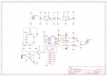
- Schematic Diagram of class D amplifier (Figure 1)
- Triangle wave (TLC555 Timer). (I am posting two pictures for clarity)(Figure 2, figure 6)
- LM393 comparator output (i am posting two pictures for clarity). (figure 3, 4)
Attachments
-
 84.5 KB Views: 8
 -
 1.1 MB Views: 5
 -
 1 MB Views: 2
 -
 1.4 MB Views: 2
 -
 1.1 MB Views: 2
 -
 3.6 MB Views: 2
 -
 3.3 MB Views: 4
 -
 1 MB Views: 3


