Class C Amplifier: Calculating the base resistor

Thread Starter

John Czerwinski

Joined Jun 19, 2017
62
I've built a Class C amplifier for educational purposes and believe I understand the major concepts on how it works. The only piece I'm struggling with is how to calculate for the base resistor. From the resources I can find, they authors talk about calculating the RC base network for 10 times the input signal time. My experience is quite different.

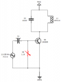
The circuit below has the following:
Input signal: 11.628 kHz (tuned to the tank circuit) @ 2v p-p
Tank circuit: C3 = 213nf, L1 = 877mH
Base clamping circuit:
C1 = 100uf
R = is a variable resistor. I've dialed it to 1.1K ohms, which produces the optimal output p-p signal. The circuit works as expected, but just lost on getting the right math.


My question is: what is the formula to correctly choose the base resistor? Any good resources on negative clamping circuit calculations?

ClassC Amplifier.png
 

Attachments

Irving

Joined Jan 30, 2016
3,841
Can you post a link to the resource you mention?

In your simulation/breadboard what is your source's output impedance?

Also, shouldn't that be uH?
Else, f = 1/2π√LC = 1/2π√(213e-9 * 877e-3) = 1/2π√(1.868e-7) = 1/2π*4.0322e-4 = 368Hz

instead of f = 1/2π√(213e-9 * 877e-6) = 11.644kHz
 

Thread Starter

John Czerwinski

Joined Jun 19, 2017
62
Thanks for the response.

1. Yes, you're correct. It should be 877,8 uH and not mH. The breadboard setup is correct and get the expected result.
2. I'm pulling the output signal directly from the tank circuit (no other load), so not sure what the output impedance is
3. Regarding the resources, I've included two. Ones a youtube video I found, the other is (below) from Electronic Devices - Floyd
Diode Clamping.PNG
 

Irving

Joined Jan 30, 2016
3,841
And c1 definitely 100u?

Running a LTSpice simulation suggests R3 has little or no effect once it get large enough to allow the transistor to turn on.

That second paragraph seems to be referring to normal AC/DC rectification/smoothing I'm not sure I recognize its relevance here.

1593615174015.png rer
 

Audioguru again

Joined Oct 21, 2019
6,647
Your schematic shows a PNP transistor but the circuit and the 2N3904 is an NPN transistor.
The 100uF input coupling capacitor has a value that is WAY TOO HIGH.
 

Thread Starter

John Czerwinski

Joined Jun 19, 2017
62
Your schematic shows a PNP transistor but the circuit and the 2N3904 is an NPN transistor.
The 100uF input coupling capacitor has a value that is WAY TOO HIGH.
Right, it's a 2N3904 NPN, even though the diagram shows PNP.

Based on the 1.1K ohm resistance, I'm assuming I could calculate the coupling capacitor to: c = 1/2pi(11628)(1100)
This gives me a coupling capacitor of 12.5nF
 

Irving

Joined Jan 30, 2016
3,841
At 11.6k Zc is = 1/2π(11.6e3 . 12.5e-9) = 1093ohm, so your coupling into the base is going to be attenuated by 6dB. The transistor is only just getting into conduction and stimulating the tank circuit. The value of the class C amp is to generate significant output power from a small amount of input. The bias should be sufficient to get the transistor turned on long enough to kick the tank circuit. I don't see a C1 R1 time constant effect there. From the video it was talking later about a separate bias circuit to generate a specific non-linear function, namely frequency doubling (or even tripling).

What is your goal in setting a specific value of R1?
 

Thread Starter

John Czerwinski

Joined Jun 19, 2017
62
At 11.6k Zc is = 1/2π(11.6e3 . 12.5e-9) = 1093ohm, so your coupling into the base is going to be attenuated by 6dB. The transistor is only just getting into conduction and stimulating the tank circuit. The value of the class C amp is to generate significant output power from a small amount of input. The bias should be sufficient to get the transistor turned on long enough to kick the tank circuit. I don't see a C1 R1 time constant effect there. From the video it was talking later about a separate bias circuit to generate a specific non-linear function, namely frequency doubling (or even tripling).

What is your goal in setting a specific value of R1?
Basically, just want to understand the calculation for R1 to optimize to getting the transistor to conduct and stimulate the tank circuit. My experimentation showed that going to low a resistance will not get the signal past the 0.7v Vbe drop (obviously). On the other hand, too high of resistance diminishes as well. In my example, seems that 1K ohm is the "sweet spot"
 

BobTPH

Joined Jun 5, 2013
8,765
There is no sweet spot. As long as R1 >> your signal output impedance, it will not have andeffect, and as it goes lower it will dampen the input, halving it when it is equal to the output impedance.

Bob
 
Top