A 1/8 stereo input. My girlfriend made me put away the project for tonight. Ill look into what you noticed tomorrow.
Again, I really appreciate your help and patience.
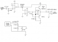
No can do unless you create a, "fake" ground at the middle of a 12 volt supply and use that for the ground symbols at the inputs of the two op-amps. Both of them require very little current, so you can just use 2 resistors and a capacitor to make the voltage at the middle hold still. Say...10k ohms each with a 10 uf capacitor connected to the most negative voltage of the wall wart.
It is ultimately up to you to measure the voltage at the collectors of the power transistors because you can see this better than I can, and you can measure it, while I completely can't (measure it).
As for the stereo input, many a beginner has come here with the pins confused on a stereo jack. I see in the 5th photo that you have a computer trying to send a signal to your amplifier. I would start by only connecting one of the channels to the amplifier in case, "shorting" the 2 channels together annoys the computer. OR...you can add 100 ohms in series with each of the signal wires to get both channels amplified without shorting the two channels together.
Do you have any kind of meter that can register some kind of AC voltage movement while measuring the alleged signal from the computer?
Are you aware that adjusting the volume control to MAX is going to cause incredible amounts of gain and turn this into a square wave generator?
Is your 10k pot linear or audio type? I would prefer a linear pot set at the middle of its range to get the second stage to have a gain of 1.
Hey #12,
Alright so I switched to a transformer regulated to 24~ Vs. The pot is audio.
And I have the input coming from my phone is the volume at half.
The voltage at npn collector is at 23.72 and pnp is at 23.4.
Now with the transformer, where does the ground come from? Ground being zero V..
I get that from the transformer comes +/- 24~ V......
The voltage at npn collector is at 23.72 and pnp is at 23.4.
/QUOTE]
That is definitely wrong. The collector of the PNP transistor should be "ground" or your most negative voltage.
This indicates a missing connection from the ground side of the power supply.
Ok, time out, my TL082 dosnt have a notch on the side to indicate top. All it has is a circle thats a different color from the rest of the DIP. I assumed that the circle indicated top. Am i correct in assuming that?
Also, my previous question. I have the + and - of the 24dc. Where to I connect the ground (zero V) to?
Alright. Getting closer, I built a filter like you had me do for the wall wart, except with the 24vdc, I used 2 22k resisters and a 22uM cap to create the fake ground.
I now have the C of both the NPN and PNP at around zero. Now I have atleast noise coming from the speaker. When I put the pot at max, the noise gets louder will I hit max, then nothing for a while, and then I can bring the pot from zero to a mid point without it going silent again. Is this indicative of something?
Ok, so, thanks to all your help, atleast audio comes out of the 4ohm speaker.
Now, when I reach a high point of the pot, the speaker cuts out and dosint come back on until I disconnect and reconnect the power.
The power transistors require heatsinks for when you get it working.
The supply shown in yellow in your post#10 will likely be a switched mode supply.
This will not play well with an analog amplifier. Get two large value capacitors say 5000 microfarads or better (one for + and one for -) and place them across the outputs of two such 12V wall warts.
Alternatively get a single 24V wall wart and connect the speaker to the centre (output) terminals of the amp through a 5000 microfarad capacitor to earth (edit to -V) and do not earth the centre point of the amp.
This will convert the amp circuit from dual to single supply. this is probably your easiest solution.
I actually I switched to 24v transformer rectified and made a fake ground with 2x22k res and a 22uM cap.
My problem is that the volume from two 2 4ohm speakers is very low. And, when i spin the 10k pot past a certain point, the sounds stops until i reset the power.
I have a 1000uf 25v cap before the speaker positive terminal. From what i read this amp can produce good volume with little distortion.
The sound i get is very low volume, and even with my phone (where the sound is coming from) volume set low, there is some distortion.
Ill attach a pic of my current set up
Thanks #12, but I actually figured it out and got it to work some what. I used what you recommended on a 12v for a fake ground, but adapted it to my 24v transformer as you can see in the last pic I posted. (except I used a 22uf instead of a 10uf). Now:
My problem is that the volume from two 2 4ohm speakers is very low. And, when i spin the 10k pot past a certain point, the sounds stops until i reset the power.
I have a 1000uf 25v cap before the speaker positive terminal. From what i read this amp can produce good volume with little distortion.
The sound i get is very low volume, and even with my phone (where the sound is coming from) volume set low, there is some distortion.
Ill attach a pic of my current set up
Either that or install a 1k to the left of the pot so that stage can't have a gain of more than 10.
Now it's time to measure and see if your input signal is the same amplitude after the first stage. If it is, the problem might be in the second stage.
If the second stage is adjustable from a gain of zero to 10, you might just have a terribly cheap speaker.
Thanks 12, Ill have to check the signals tomorrow gata go do things that arent amp/audio electrics related unfortunately. I have been obsessing learning about all this last few months
 Facebook
 Google
 GitHub
 Linkedin
")