Class AB Amplifier over-heating puzzle

Thread Starter

Nicholas Lee

Joined Apr 29, 2017
8
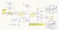
I have attached a picture of the Class AB amplifier circuit for reference.

The whole PCB has 9 sets of these transistor amplifiers, and I am only showing the drawing for one of these for simplicity.
The voltage input to the amplifiers comes from a DAC (with a level-shifting circuit).

For seven of the amplifier circuits, the output transistors are cold, but in two of them the output transistor temperature steadily rises without limit and the board must be switched off within 60 seconds to prevent damage.
I can't detect any short-circuits in the anomalous circuits, and indeed, if I direct the DAC to output a sinewave, I see a nice clean bipolar sinewave coming out of the rapidly heating amplifiers. So they are 'working' properly as amplifiers, but they are getting too hot.

I have measured the biasing diodes, and they all seem to have 0.55V across them.
At this point, the output of all the amplifiers are unconnected, so there is no load.

I thought I would put this problem out to the community hive-mind to see if anyone can suggest an better theory for why some of the transistors are over heating and others aren't.

My current theory (which could be wrong) is that the biasing diodes aren't thermally-coupled to the output transistors so their bias voltage does not go down when the power transistors heat up. This is allowing the output transistors to go into thermal run-away.
Why this only happens in only a couple of the otherwise identical circuits is the mystery, and I am currently putting it down to minor component variances and bad luck.
 

Attachments

crutschow

Joined Mar 14, 2008
38,331
Check the value of R10 and R11.
If they appear okay, you might try replacing them with larger values, say 12k-15k.
Use 1% resistors.
 
A few comments:

The output of IC3 and IC4 should have resistors. Something for Ib to drop across. That sort of stuff drove me nuts on my first real analog design. V = ib/(near zero output Z OF AN OP AMP ) can make a big number. I didn't look at the datasheets.

Always remember to have a place for ib to go. I solved my issue with like a 200 ohm resistor.
1e-12 A * 200 is not too big, but Voffset/~0 is very big.

Is it oscillating?
 

Thread Starter

Nicholas Lee

Joined Apr 29, 2017
8
Check the value of R10 and R11.
If they appear okay, you might try replacing them with larger values, say 12k-15k.
Use 1% resistors.
Hi,
Yes, the resistors measure as 10k, 0.1% precision resistors (no expense spared!)

Is there an engineering reason why a larger resistance value might be better?

Regards,
Nicholas Lee
 

Thread Starter

Nicholas Lee

Joined Apr 29, 2017
8
A few comments:

The output of IC3 and IC4 should have resistors. Something for Ib to drop across. That sort of stuff drove me nuts on my first real analog design. V = ib/(near zero output Z OF AN OP AMP ) can make a big number. I didn't look at the datasheets.

Always remember to have a place for ib to go. I solved my issue with like a 200 ohm resistor.
1e-12 A * 200 is not too big, but Voffset/~0 is very big.

Is it oscillating?
Hi,
Interesting, but I can't quite see how this might cause the observed problem in this case.
The op-amps and DAC all seem to be well behaved.

Heat dissipation due to RF oscillatory oscillation is a good guess, but If there is an oscillation then it is above the ability of my 60MHz to display it.

Regards,
Nicholas Lee
 

crutschow

Joined Mar 14, 2008
38,331
Interesting, but I can't quite see how this might cause the observed problem in this case.
My assumption is that the heating is caused by too much bias current in the output transistors.
The bias current is determined by the voltage across the two base diodes and that is affected by the current through the diodes, which is controlled by the value of the two resistors.
 

Thread Starter

Nicholas Lee

Joined Apr 29, 2017
8
In class AB output stages I usually have resistors in series with the emitter of each output transistor. The resistors are there to reduce the chance of the thermal run-away that you suspect.
That's interesting, are you able to elaborate on this, and explain how emitter resistors affect the biasing and/or thermal runaway?
Can you illustrate with some relevant design calculations for these resistors? Show me the maths!

The target load impedance is between 4 and 8 ohms, DC-coupled. No, it is not a speaker coil!

FYI: I used the following source for the AB amplifier design: http://www.electronics-tutorials.ws/amplifier/class-ab-amplifier.html
 

ronv

Joined Nov 12, 2008
3,770
That's interesting, are you able to elaborate on this, and explain how emitter resistors affect the biasing and/or thermal runaway?
Can you illustrate with some relevant design calculations for these resistors? Show me the maths!

The target load impedance is between 4 and 8 ohms, DC-coupled. No, it is not a speaker coil!

FYI: I used the following source for the AB amplifier design: http://www.electronics-tutorials.ws/amplifier/class-ab-amplifier.html
Here is a write up on some biasing methods (and problems). Are the diodes and transistors all on the same heat sink?
http://www.seas.upenn.edu/~ese319/Lecture_Notes/Lec_22_ClassAB_Amplifier_12.pdf
 

yevgeny

Joined May 20, 2017
15
Problem is tolerance of I/V characteristic of transistors and diodes. In your two stages, voltage drop across diodes higher than Veb of transistors - most of the resistor current goes through base-emitter (A-CLASS). Resistor in emitter may help, but mostly for overall temperature
stability. The best solution in this case - using the same transistors (like output transistors) in diode application instead D1 & D2.
 

Thread Starter

Nicholas Lee

Joined Apr 29, 2017
8
Thanks guys.

Ok, I have now gone the whole 9-yards and simulated all the suggestions and their combinations in Spice.

This has included multiple simulation sweeps over a range of different temperatures, both with and without the bias diodes on the same simulated "heatsink" as the output transistors, and both with and without emitter output resistors, and both with and without a load on the amplifier.

The simulation results predict that most of the real-world problems are due to the fact that the heatsink isn't present yet, so the diodes aren't tracking the temperature of the transistors as they heat up.
In simulation, putting a 1 ohm resistor in the emitters of the power transistors helped reduce the quiescent currents and improved the thermal stability both with and without a thermally-coupling heatsink. (although retrofitting these resistors on the existing physical PCB will be a PITA)
It is less obvious from the simulation 'why' these resistors works so well, but they certainly do.
The 10K biasing resistors could not be increased in value further without causing output voltage clipping. They already appear to be maximally large for the design. If they had been lower in value to start with (e.g. 1K), then the quiescent current would indeed have been far higher.
The overall output voltage swing was found to be limited by the output current of the op-amp multiplied by the hFE of the transistors.
 

crutschow

Joined Mar 14, 2008
38,331
...............In simulation, putting a 1 ohm resistor in the emitters of the power transistors helped reduce the quiescent currents and improved the thermal stability both with and without a thermally-coupling heatsink. (although retrofitting these resistors on the existing physical PCB will be a PITA)
It is less obvious from the simulation 'why' these resistors works so well, but they certainly do.
Remember that we are talking about millivolts of difference in the base-emitter voltage due to the change in temperature.
A 1 ohm emitter resistor give a mV of negative-feedback difference for a mA of current change, providing a strong stabilizing effect to the emitter current.
 
Top