Class AB Amplifier Output

Thread Starter

elec_eng_55

Joined May 13, 2018
214
Hi:

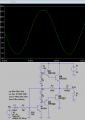
I have attached a class ab amplifier schematic.
The formula Pac = VCEQ^2 / 2 * RL
Is Pac in rms watts?

If Pac =2.25 Watts rms and RL = 8 Ω

Then VCEQ = (2 * Pac * RL) ^1/2 = 6 volts

Input signal is a 1Khz sine wave.

Doesn't this mean that the output signal can swing almost +/- 6 volts?

My question is this. Why can I only get a clean output signal of approximately +/- 1 volt?
It just doesn't make any sense to me.

David
 

Attachments

Last edited:

AnalogKid

Joined Aug 1, 2013
12,129
Your circuit has no voltage gain. For the output to swing its full possible range, the input must also.

For a single-supply audio amp, the supply voltage equals the maximum peak-to-peak output waveform amplitude. Divide this by 2.828 (2 x (sqrt 2)) to ge the equivalent RMS voltage. Use this to get the max output power (RMS). In your case, 2.25 W.

But the p-p output voltage is not 12 V because of the base-emitter voltage drop in each output transistor. Assuming the textbook 0.6 V, the max output power drops to 1.8 W. Note that Vbe for power transistors is larger than the textbook 0.6 V,

There is no standard 1% resistor value of 353 ohms.

Peak current into the 8 ohm load is almost 1 A. For the TIP31, this means that the input signal might have to supply 10 mA or more. That's a lot for an audio source.

ak
 
You should also post your schematic in PDF form.

I pondered this problem when building a "100 W/ch" amp. The amp supposedly was very good for driving Electrostatic speakers so they used a 3A RMS AC transformer to get a +-50V bi-polar supply for two channels. \

I actually used a 3A supply for each channel, doubling the rating.

The DC value of current is like 0.62 * 3, so that's the current I have to work with. You can work with the rails of +-50V with some drop and you can work with the power supply current. At 3A*3A*8, it's only 72 Watts and that was the limiting factor. I do have 10,000 uF of capacitance on each rail (40,000 uF total), so I can get some high peak currents.

A friend and I did a comparison with a Macintosh valve amp (<10 W) and Voice of the Theater speakers. Bass was great with my amp and lousy on his. The horns seemed louder with the Mac amp. The horns needed voltage.

At home I have a 500 W AC voltage regulator on the amp which helps quite a bit.

He likes classical which makes the horns a great fit and I like Folk which makes dome tweeters (30 W) a good fit. I can easily pop a 1A tweeter fuse. My amp has no protection except a fast acting 3A fuse for the speakers.

I should not say that. With the soft-start, the protection circuit will protect against an NPN and PNP output transistor reversed with one resistor destroyed. If a rail should fail, that resistor would pop too.

The amp is a version of the Leach Amp with an unrolled off BW of 0 Hz to 800 kHz, so it handles transients very well. BW is restricted to 0.5 Hz to 40 kHz.
 

Thread Starter

elec_eng_55

Joined May 13, 2018
214
hi,
That circuit is a current amplifier, it has no voltage gain.
The output voltage is approx the input voltage.
e
I understand that there is no voltage gain. If I apply a 1 volt peak signal,
I get 0.844 volt peak out. The ouput power is P = 0.844^2 / 8 Ω = 89mW peak
or 63mW rms?
 

Thread Starter

elec_eng_55

Joined May 13, 2018
214
Your circuit has no voltage gain. For the output to swing its full possible range, the input must also.

For a single-supply audio amp, the supply voltage equals the maximum peak-to-peak output waveform amplitude. Divide this by 2.828 (2 x (sqrt 2)) to ge the equivalent RMS voltage. Use this to get the max output power (RMS). In your case, 2.25 W.

But the p-p output voltage is not 12 V because of the base-emitter voltage drop in each output transistor. Assuming the textbook 0.6 V, the max output power drops to 1.8 W. Note that Vbe for power transistors is larger than the textbook 0.6 V,

There is no standard 1% resistor value of 353 ohms.

Peak current into the 8 ohm load is almost 1 A. For the TIP31, this means that the input signal might have to supply 10 mA or more. That's a lot for an audio source.

ak
The load current per sim is 100mA?
 

ericgibbs

Joined Jan 29, 2010
21,442
The 'usual' way is a higher single or dual power voltage and lower speaker impedances say 4 Ohms.
Remember its the (V^2)/Rload effect.
Try raising your Vsup to say 24Vdc
 

Thread Starter

elec_eng_55

Joined May 13, 2018
214
The 'usual' way is a higher single or dual power voltage and lower speaker impedances say 4 Ohms.
Remember its the (V^2)/Rload effect.
Try raising your Vsup to say 24Vdc
Ok. I raised the supply to 24 volts and the input signal to 3 volts.
The output is still slightly less than 1 watt.

When you apply the formula, Power = VCEQ^2 / 2 * RL = 12^2 / 2 * 8 = 9 watts rms


It seems like a no-win.
 

Thread Starter

elec_eng_55

Joined May 13, 2018
214
I do not get it, what you expect from this formula to tell you?
According to an engineer that I know, that formula is supposed to be the total
rms output power if you have Vcc = 24 volts, and a load of 8 ohms. He also
said that the output swing should be capable of slightly less than +/- 12 volts if
the input signal is slightly higher than 12 volts.
 

Jony130

Joined Feb 17, 2009
5,598
that formula is supposed to be the total
rms output power if you have Vcc = 24 volts, and a load of 8 ohms.
This formula will give you a rough approximation (ballpark figure) of maximum average output power (active/real power).
But this formula does not work always. And remember that there is no such a thing as an RMS power.

For your circuit we have

IL_max = (Vcc - V_Cap2 - Vbe)/(RB/(β+1) + RL) ≈ (12V - 6V- 0.7V)/(353Ω/81 + 8Ω) ≈ 0.42Apeak

Hence Vout_max ≈ 0.42A*8Ω ≈ 3.36Vpeak. And the average power is P = (3.36V)^2/(2 *8Ω) = 0.7W (for a sinewave at the output) for example for THD = 10% the maximum output power will be 1.65 times the average power for a sinewave.
 
Last edited:

Thread Starter

elec_eng_55

Joined May 13, 2018
214
This formula will give you a rough approximation (ballpark figure) of maximum average output power (active/real power).
But this formula does not work always. And remember that there is no such a thing as an RMS power.

For your circuit we have

IL_max = (Vcc - V_Cap2 - Vbe)/(RB/(β+1) + RL) ≈ (12V - 6V- 0.7V)/(353Ω/81 + 8Ω) ≈ 0.42Apeak

Hence Vout_max ≈ 0.42A*8Ω ≈ 3.36Vpeak. And the average power is P = (3.36V)^2/(2 *8Ω) = 0.7W (for a sinewave at the output) for example for THD = 10% the maximum output power will be 1.65 times the average power for a sinewave.

What is V_Cap2? And where does the β of 80 come from?
 

Audioguru

Joined Dec 20, 2007
11,248
Your circuit uses the input signal to turn OFF the output transistors and the 353 ohm resistors turn on the output transistors only a little.
Most audio amplifiers use a driver transistor to turn on one output transistor with plenty of current then use bootstrapping to turn on the other output transistor with plenty of current. Negative feedback is used to reduce any distortion. The output voltage swing can be almost the supply voltage.
 

Thread Starter

elec_eng_55

Joined May 13, 2018
214
Using the schematic that have provided below.
Vcc = 30 Volts
RL = 8Ω

If you use Pmaxout(peak) = Vcc^2 / RL = 30V^2 / 8Ω = 112.5 watts peak
In reality, the sim supplies 4.85 volt peak output and a 2.94 watt peak ouput
power with a 2 volt peak sine input. Any greater input produces a garbage
signal.

Two questions: 1) Why would the estimate of 112.5? be so different than 2.94 w?
2) Because of such a discrepancy, how does a person ever
figure out what design parameters are needed just to get
what is needed? There is a big difference between 112.5
and 2.94. There must be a scientific approach to this.

David
 

Attachments

Last edited:

crutschow

Joined Mar 14, 2008
38,505
There must be a scientific approach to this.
There certainly is.
First you need to do the correct calculations.
The theoretical peak-to-peak voltage is 30V, giving a 15V peak output.
That drops the theoretical power by a factor of four.

Second you need to realize that the circuit as shown, cannot go rail-to-rail on the output.

Then you need to to calculate the bias points so the output is biased at near 1/2 the supply voltage ( or a little higher for that circuit since the negative output clips before the positive output.

Here's the circuit with modified bias that gives ≈16W peak power out:

upload_2018-12-22_11-28-23.png
 

Audioguru

Joined Dec 20, 2007
11,248
Instead of using driver transistors to turn off the output transistors, I use the driver transistors to turn on the output transistors.
Then the driver transistors do not need to drive a high current in your 100 ohm resistors that are not needed. I did not bother adding a 1k base-emitter resistor to each output transistor.

Instead of reducing the gain with an emitter resistor on the 3N3904 that also reduces the output voltage swing, I use the 100k resistor to provide AC and DC negative feedback.

Of course I biased the darlingtons with 4 diodes.
Bootsrapping will add a little more output voltage swing.

Your 100uF input capacitor had such a high value that it would take "an hour" to charge and it would pass earthquake frequencies.
 

Attachments

Top