Class A amplifier efficiency

Thread Starter

GibonCZ

Joined Nov 30, 2019
5
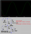
Hi all , is there any way to calculate the efficiency and gain of a Class A amplifier without taking any measurements but knowing all the component values ? Im using a NPN 2N4401 transistor and have a gain of about 30. Just wondering if there any formulas to get theoretical values. I found a formula for class B but no luck for class A so far :)
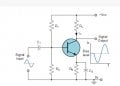
Schematics used below.
Thanks
 

Attachments

Thread Starter

GibonCZ

Joined Nov 30, 2019
5
You can calculate base, emitter and collector voltages then use Ohm's Law to calculate their currents.
Your transistor has no load then why is its gain so low?
ok thank you
not quite sure why, I've used 4.7k for top resistors and 1k for bottom.
any idea on the efficiency achieved ?
 

MisterBill2

Joined Jan 23, 2018
18,502
The emitter resistor in a common emitter amplifier is used to stabilize the steady state base bias, and to provide negative feedback that reduces distortion. Of course, negative feedback also reduces gain, but in some applications low distortion is more important than maximum gain.
The efficiency of a class "A" amplifier is always low, never above 50%, usually closer to 40%. That is because there is always a fair amount of current flowing, so that the active device is operating in it's most linear operation area.
 

Audioguru again

Joined Oct 21, 2019
6,691
The resistor values for a transistor are designed and calculated, not just guessed.
Your circuit does not have "top and bottom" resistors. Instead it has R1, RL, R2 and RE.

Please post the schematic of your transistor circuit showing all resistor and capacitor values and its power supply voltage. Then we can see why its gain is so low.

Efficiency involves the power delivered to the load but your circuit has no load then its efficiency is ZERO.

If you want high efficiency then use a Cmos opamp, it operates in class-AB.
 

Thread Starter

GibonCZ

Joined Nov 30, 2019
5
The resistor values for a transistor are designed and calculated, not just guessed.
Your circuit does not have "top and bottom" resistors. Instead it has R1, RL, R2 and RE.

Please post the schematic of your transistor circuit showing all resistor and capacitor values and its power supply voltage. Then we can see why its gain is so low.

Efficiency involves the power delivered to the load but your circuit has no load then its efficiency is ZERO.

If you want high efficiency then use a Cmos opamp, it operates in class-AB.
right, RE &R2 = 1k , RL&R1 4.7k . tested it with 100mV - 200mV Vp with frequencies of 100-300 and had a gain of about 30. Is that low ? saturation was at 9.04V due to 9V Vcc I suppose ? ddddd.JPG
 

MrAl

Joined Jun 17, 2014
11,474
right, RE &R2 = 1k , RL&R1 4.7k . tested it with 100mV - 200mV Vp with frequencies of 100-300 and had a gain of about 30. Is that low ? saturation was at 9.04V due to 9V Vcc I suppose ? View attachment 199698
Hi,

I might expect a gain of higher than that even at 100Hz but the 1uf cap is a little too low i think.
Try a bigger cap for the input capacitor, like 10uf or another 22uf for example.

We can develop a formula if you like but the gain will depend on the Beta of the transistor as well as the component values.

Without the 22uf cap the gain is Rc/(re+RE)*B/(B+1) where B is the Beta, but with the 22uf cap it goes higher because it becomes related to Rc divided by the impedance of the emitter circuit and that boosts the gain up much higher..
 

Audioguru again

Joined Oct 21, 2019
6,691
Your gain was low because the values of the capacitors were calculated to cut low frequencies, and the input level was much too high causing clipping (saturation).
I simulated it and found your gain was 59.6 times when its input level was turned down so that there was only a small amount of clipping.
I increased the capacitor values so that the level of 200Hz was not cut.
I calculated much higher values for R1 and R2.
 

Attachments

MrAl

Joined Jun 17, 2014
11,474
Hello again,

I did a more comprehensive set of calculations and found the gain to be 25.63183754407431 at 100Hz.
A simulation i did came out to 25.6318 but that's all the digits it provided.
Keep in mind that is at 100Hz only.
The simulation model for the transistor was the small signal model with re only.
 

MrAl

Joined Jun 17, 2014
11,474
Hello again,

The complete solution formulas can get a little long.
For example, here is a formula for calculating the output DC voltage knowing all the resistor values and the supply voltage and Vbe and the Beta.
VdcOut=
(-Vcc*B*R2*RL+Vbe*B*R2*RL+Vbe*B*R1*RL+Vcc*B*R2*RE+
Vcc*R2*RE+Vcc*B*R1*RE+Vcc*R1*RE+Vcc*R1*R2)/(B*R2*RE+R2*RE+
B*R1*RE+R1*RE+R1*R2)

As you can see it's a little long just for the output DC voltage. However, that formula calculates VdcOut in one fell swoop without having to calculate anything else and no iterations required.

This formula uses a model with current controlled current source and Vbe, and 're'. It is similar to the small signal model except it includes Vbe also. The value of 're' is contained within the formula so no need to calculate it separately unless you want to do a simulation and then re=VT/Ie where VT=0.026 typically.

To test that formula in a simulator keep in mind that the thermal voltage VT (usually taken to be 0.026v) is internal to the transistor yet you will end up with 're' where Vbe is across the base and the bottom of 're'. This means you must set the internal Vbe to 0.7 minus 0.026v. That will be a constant voltage source. After that if you were to measure the external Vbe it would be from the 'base' to the bottom of 're' not the top and it would be exactly 0.7 volts.

I tested it with Vbe=0.7 and VT=0.026 and results agreed exactly with a simulation, and a later calculation matched the AC gain calculation exactly too. So the formula is exact for the model being used which includes Vbe, VT and thus 're', and a current controlled current source.
 
Top