Circuit with output depandant on input impulse lengh

Thread Starter

lebowsky

Joined May 4, 2024
3
Hi,


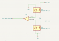
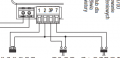
I need a simple circuit that has one input and two outputs. It should work as follows: when input is set to HI for less than 1 second ==> output A is set to HI for set time, when input is set to HI for more than 1 second ==> output B is set to HI for set time. I know it could be done easily with MCU but I wonder if there is a way to do it with simple logic ICs.


Thanks, Lukas
 

WBahn

Joined Mar 31, 2012
32,707
There's quite a bit that you are leaving unspecified, such as when the outputs should go HI. Or what happens if the input goes HI again while one of the outputs is already HI. You are also implying that only one of the outputs is HI at any given time, is that correct?

This sounds like some kind of course assignment. Is it?
 

BobTPH

Joined Jun 5, 2013
11,466
So let’s assume the input is low and both outputs are off.

The input goes high. What happens? is A activated? Or does it only activate when the input goes low before 1 second?

At 1 second B activates.

While B is active, what happens if the input goes low then high again while B is active?

If the input goes low again within a second does A activate even though B is still active?

A state diagram would be a good way to describe the behavior in all condition.
 

Thread Starter

lebowsky

Joined May 4, 2024
3
This circuit will connect household intercom to the gate automation system. Intercom provides simple 12V output active when host presses button on house unit. The automation system has two inputs A and B, A when is connected to ground opens gate fully, B when is connected to ground open gates partially so a person can come through. I guess I need two relays controlled independently.


Default state of circuit is that input and both outputs are at LOW. When short time signal from intercom is send output A goes HI so it can activate relay and set automation system input A on LOW. When long time signal from intercom is send output B is HI and the second relay is activated. Both outputs should go back to default after activating relays. The time of input signal should determine wich output turns on.


I attached simple schematic, opamp symbol depicts circuit I need. Relays may be obsolete if the outputs are kept at HI during default state. I hope it clarifies a bit.
 

Attachments

Last edited:

MisterBill2

Joined Jan 23, 2018
27,193
It can be done with retriggerable one-shot multi-vib ICs But it makes more sense to have each function triggered by a sensed audio signal, either high or low. Two tones .
 

AnalogKid

Joined Aug 1, 2013
12,050
There is only one +12 V signal line.

If it goes high and then returns low (terminates) in less than 1 second, output A is activated for a fixed (unknown) time period *after* the input signal has returned low. It is assumed that the incoming signal will not go high again during this period, but if it does, it is locked out. Once a short pulse comes in, the system rejects all other inputs until the A output has timed out.

If the input signal remains high for more than 1 second, output A is locked out and output B is activated for a fixed time period. Is this always the same period that the A timer is set to, or can this be a different time? Either way, the input is again locked out during the B time period.

Yes - No - ?

This sounds like two or three (depending on the B timer) monostables plus some simple gating. No microcontrollers; maybe two 555's. depending on what the output devices are.

What do the A and B output signals drive? Do the output devices need to be relays, or can they be transistors switching a system input to either GND or +12 V?

Where are you located, and what is your skill set for wiring up a small circuit on perf-board? Also, what powers this circuit and where will it be located?

ak
 
Last edited:

MisterBill2

Joined Jan 23, 2018
27,193
OK, I had guessed that the intercom had a communication link to the location that had the gate control module. That is why I had suggested a tone command. The tone sensor would then activate the gate controller system. But if the whole connection is a single DC link then the scheme must be different.
Is there any feedback communication that would report that the gate was closed, open fully, or ajar for a person to pass??
I am guessing that the gate controller only needs a short button press of either the "open" button or the "close" button to initiate a move to fully open or fully closed, with internal limit switches to halt motion at the end of travel. Or is the local control scheme different from that??
 

AnalogKid

Joined Aug 1, 2013
12,050
So far it sounds like an open-loop system. The gate is operated for one of two time periods, one just long enough to allow a person to enter and one longer to retract the gate enough for e vehicle. No word on what causes the gate to close.

The logic is more tricky than at first glance because the input signal trailing edge does two different things.

ak
 

MisterBill2

Joined Jan 23, 2018
27,193
OK, here goes the logic description first, because that way it is simpler to generate the device sequence, since this will require a few logic elements. The timers are CD 4528 devices with Q and Q{not) ouputs. So here it is:
A short pulse triggers a timer less than one second. The Q output is AND with the inverted trigger to only be true if the button signal ends during that first second. So that signal is the first required trigger for the #1 output timer to be started.
For the second output, a different timer is also started at the initial input, That time complete output Q2(not) is AND with the button signal ON to trigger the #2 output timer ON.
Asa safety addition, in case there is an additional pulse or pulses within some very short time, a counter (CD4017) is incremented with each button press and if it counts more than two pulses it resets and inhibits all actions for about ten seconds. That can also serve as an emergency stop function.
 

Thread Starter

lebowsky

Joined May 4, 2024
3
There is only one +12 V signal line.

If it goes high and then returns low (terminates) in less than 1 second, output A is activated for a fixed (unknown) time period *after* the input signal has returned low. It is assumed that the incoming signal will not go high again during this period, but if it does, it is locked out. Once a short pulse comes in, the system rejects all other inputs until the A output has timed out.

If the input signal remains high for more than 1 second, output A is locked out and output B is activated for a fixed time period. Is this always the same period that the A timer is set to, or can this be a different time? Either way, the input is again locked out during the B time period.

Yes - No - ?

This sounds like two or three (depending on the B timer) monostables plus some simple gating. No microcontrollers; maybe two 555's. depending on what the output devices are.

What do the A and B output signals drive? Do the output devices need to be relays, or can they be transistors switching a system input to either GND or +12 V?

Where are you located, and what is your skill set for wiring up a small circuit on perf-board? Also, what powers this circuit and where will it be located?

ak
Theese are inputs on gate automation mobo that desired circuit should control. PIN 2 is GND, PINs 3P and 7 will run programmed function when switches are closed. As I said, both relays or transistors should be fine. I have experience with producing simple PCBs.
 

Attachments

AnalogKid

Joined Aug 1, 2013
12,050
1. For the two output pulses A and B that drive the switch inputs, do the A and B pulse widths affect the controller output, or do they just have to be wide enough to be seen as a switch push? For example, can both the A and B outputs be 1 second?

2. How much current goes through those switches? For example, the switch current for my garage door opener is almost 700 mA.

3. For the B output, the one that pulses after the 1-second discrimination window - Does that pulse start when the high input crosses the 1-second mark, or does it start when the long input pulse goes low (sometime after the 1-second point)?

I'm trying to keep the design to one IC (plus possible output drivers). Right now I'm at one hex inverter plus one 555.

ak
 
Last edited:

MisterBill2

Joined Jan 23, 2018
27,193
OK, I described the logic to do it in post #9, and added an "E-STOP" function as well. The logic is based on the requirements provided in post #1. The emergency stop function would be triggered by multiple pulses, more than three. Of course the logic presumes that the decoder will be powered by other than the pulse used for triggering.
 
Top