 Facebook
 Google
 GitHub
 Linkedin
Greetings all.
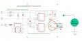
I was hoping someone might be able to help. I built the attached circuit (not my design...) to drive the tachometer movement in my vintage car. the circuit works great on bench but not in the car. I figured out why... the meter movement in the tachometer is grounded to the case, and it's not possible to 'unground'. The circuit won't work with the grounded movement.
is there a simple way to adapt the output of the circuit to be compatible with the ground referenced meter movement?
Any help is appreciated!
Attachments
-
 42.5 KB Views: 38

")


