Circuit to add a spike to a square wave

panic mode

Joined Oct 10, 2011
5,040
12V is fine. problem is your square wave generator. it does not produce clean square wave - rising time is too long. you really want steep flanks with nice and sharp corners. you could fix that by running signal through additional stage such as comparator or Schmidt trigger and adding buffer.

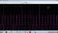
example using really slow rise time (12ms). in simulator this appears as tilted line before spike. i have left falling edge steeper for comparison,...

1727459836323.png

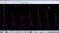
example when signal rises faster (2ms is ok):
1727459855580.png
1727459868486.png


with sufficiently short rising time of the square wave, the spikes would be even larger if not limited by Zener diode:
1727460404876.png

and the Zener is used for that very reason... to protect transistor:
1727460551190.png

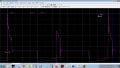
so keeping rise time at 2ms, and just changing zener diode to 110V version, peaks can be higher and still safe for transistor....

and this works just fine when load is added. such as 10k or even less. with really low load values like 3k or so, spikes do become shorter... but... 3k is a good order of magnitude lower resistance than what actual unit should be (if it is anything like circuit revealed by MrChips).

1727460814182.png
 
Last edited:

panic mode

Joined Oct 10, 2011
5,040
i guess you could use more help so here is an example of a circuit that may help fix your toubles...
to be sure that what suggestions are suitable you need to get some data of the real values - peak voltage, duration, load resistance... without such data all that is shown here is just a guess...


anyway, this example (and it is just an example) uses following:

1. separate 12V supply (V2) to power it rather than overloading weak output of the signal generator.

2. assuming signal generator is unable to produce high quality signal. as a demo i actually turned it into a sine wave (V1). and sine wave is not a good square waveform by any standards.. actual generator should be able to do much better specially since now it is only driving comparator input (and that is high impedance, so not much of a load...).

3. use comparator to re-shape signal we get (sine or square wave or whatver) into a clean square wave. Just about any comparator will do like trusty LM311 but i do not see in the LT Spice library so shown part is just a first thing i clicked on to use as a substitute.

4. comparator gives us the square waveform but its output cannot handle much... most are limited to 10mA or so. so we need a buffer... also comparator output pulls low so polarity is not suitable to drive output stage (we need rising edge to be fast). therefore Q1 is added. i know this is adding parts but it is better to design circuit in stages. according to simulator rising time here (Q1 collector) is only about 1us (0.001ms) and that is nice.

5. capacitor still turns square wave into a narrow pulse to trigger spike generator. but it also adds negative spike on second edge. this can be removed by diode.

6. spike generator does the rest... here i changed to mosfet. and made sure to use inductor with low Rdc. if you use the crappy little inductors with 150 Ohm DC resistance, output spikes are going to be much lower.

7. resistor R2 was added to simulate load... it is not to be used in real circuit. since we are using separate 12VDC supply, i no longer care about low current consumption. want to drive even heavier loads (hence low value 2.2k resistor). actual load should never be this low, but this is a good stress test to simulate things and see if circuit can work. if it can drive low resistance loads, it should have no problem with others. i suggest to try things out in simulator as well. once you have things setup in simulator, you can play with values to see how circuit behaves.

about graphs:
1. Va and Vb are comparator inputs (points A and B). Vb is fixed so when ever Va is larger than Vb, output goes low and turns on Q1.
2. Output of Q1 (point C in schematics) is shown in second graph. note that sides of this square wave are not really square. well the rising edge is (Which we care about) but the trailing/falling edge is not (not important here).
3. M1 gate voltage. rising edge is steep (thanks to Q1), falling edge is not fast and the bottom is rounded but - we do not care. that rounding is due to capacitor. if really wanted, we could shape this signal too to make it nice square pulse of desired width.
4. output spikes reach what should be sufficiently high level. i do not know what is sufficient for you. initially we worked 30V, then 75 so here is 200V.
5. M1 current peaks are only about 80mA and narrow. so overal consumption is still very low. And for good measure, V2 has bypass capacitors.

1727478024999.png
 

panic mode

Joined Oct 10, 2011
5,040
don't forget... you need to determine correct pulse height and duration. if those are not known, there is no guarantee that any circuit will produce compatible signal
 

Thread Starter

crazyquiff

Joined Jul 25, 2024
24
don't forget... you need to determine correct pulse height and duration. if those are not known, there is no guarantee that any circuit will produce compatible signal
Thanks - not sure what you mean by "correct pulse height and duration" . I have the input form and the required form shown in images before.

If I put a square wave rather than a sin wave the output has two peaks - I suspect that is because it is too clean a square wave - can I add a capacitor to slow up the leading edge in the sim? will try - didn't make a difference :(

Note: load resistance is 38k ohm

I can swap around with zeners to get the peak voltage
 

panic mode

Joined Oct 10, 2011
5,040
It is conceivable that DUT may not respond to spikes that are too narrow. Load is 38k and it does not make much of a capacitance to filter them out... Or smooth them out enough (reduce peak) that they are not reliably detected by DUT. So i would use scope to find out what is spike peak voltage and duration really are on a working system. Then one can simulate circuit to compare the test sikes
 

BobTPH

Joined Jun 5, 2013
11,564
Am I missing something?

The actual signal shown in #47 has a period of 560ms. The faked version had a period of 60ms. Nearly 10 times shorter.
 

panic mode

Joined Oct 10, 2011
5,040
hmmm.... you are not alone...

i am not sure how to interpret what that image shows and don't feel like reading manual for that scope software.
it does look like period is 560ms and voltage is...i don't know... 4V per division?

previous posts (like #9 ) stated that period is supposed to be much shorter than 590mS, more like 5-30mS. so things that matter are height and duration, not how often the spike is triggered. since the period can be as short as 5ms (or shorter), the spike need to be short, probably under 1ms.

if the following image shows period as 560ms long, it would appear that spike width is roughly 1/10th of that, which is 56ms. that is way too long for above mentioned timing.

1727722585185.png
 

BobTPH

Joined Jun 5, 2013
11,564
I originally doubted that the lack of a spike had anything to do with the failure to trigger the counter. Nothing since has altered that opinion.

It certainly seems that a motorcycle tach would have to handle pulses at up to 8000 RPM, which would be 7.5 ms. So who knows what the problem really is.
 

MisterBill2

Joined Jan 23, 2018
27,684
OK, so there are different pulses. Evidently there are differences in the secondary connections to the four spark plugs. That looks like a miss-fire trace on a SUN ignition system analyzer.
 

simonnovak

Joined Oct 3, 2024
12
If I were in your shoes, I'd consider using an inductor with a carefully timed flyback diode setup. The key idea here is to use the energy stored in the magnetic field of an inductor. When the current rapidly stops, that energy gets released as a voltage spike. This approach can give you that leading-edge spike you're after, potentially boosting it up to 30V.

Another idea would be to add a capacitor in series with a fast-switching transistor to momentarily store and discharge energy when the leading edge hits. This could create a sharp peak, and you can tweak the component values to dial in that 30V mark.

Experiment with both approaches to see which fits your needs better. You might need to play with different inductor and capacitor sizes, but that's part of the fun!
 
Top