Are you sure it doesn't need and inverted input signal?
Some tacho's rely on a falling edge to trigger, so try a normally high (12v) that falls to ~0v for a few ms, then returns high.
zener diode controls height of the spike. L1 is used to store energy.
R1C1 control define time constant.
i was not sure what to expect but i guess you are building a test rig to drive maybe couple of things, so i beefed it all up a bit. it is likely that smaller transistor will do too but C1 would need to be reduced to limit output current.
yup... without it the spike would be just 0.7V above 12V rail (due to forward voltage of D3). zener is used to clip it at desired level to protect transistor. so it can be up to 12V+0.7V+30V=42.7V. using 18V zener for example that cap is reduced to about 12V+0.7V+18V=30.7V
this gives you pretty good control over peak voltage circuit produces.
looking at the circuit by MrChips, current draw is tiny and depending on trimpot position input voltage may need to be substantial. so one can increase inductor to something like 68mH and use Zener with higher voltage. 75V zener would allow peaks of 88V.
There is a capacitor at the SAK 215 input on pin-2. The other end of the capacitor is at GND on pin-1.
It would be nice to know the value of the capacitance they used. The sample circuit diagrams show 220 pF and 68 nF.
I would replace it with about 10 nF.
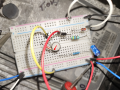
the circuit you built seem to be the based on version from post 19.
what are the part numbers of used diodes and transistor?
and did you have to have the resistor lead passing over transistor like that? it is precariously close to a tin can which is collector.
.... oopsie... TS deleted own post while i was replying.....
12V relay may only need few mA to turn on... many have coil resistance 300-900 Ohm. and this circuit does draws more...
there is no free lunch. to create higher voltage from low voltage (12V), you need higher current at that low voltage.
but if one knows the load, component values can be adapted to optimize (reduce) current draw. and after MrChips shared some variants of the circuit, i did just that - circuit in post 26 peaks at just 30mA while capable of decent voltage spikes.
if you do not need higher voltage, you can keep 30V Zener you have now.
1n4761 is rated 1W so at 75V that would allow continuous current of 1W/75V=13.3mA. that is 100% duty cycle. the spikes are very short and current is lower so yes, that will be fine. also check the specs of your square wave device, you need to know the specs and add buffer if needed.
Looking at post #1 it seemed obvious to me that the TS was wanting to simulate the pulse at the "points" terminal of an old ignition system so to be able to test the tachometers from that era. Some of those tach circuits are vastly simpler than the 555 timer scheme. Even the LM2917 circuit is simpler than the 555 scheme, and probably much more stable as well.
Here is an idea: make a digital recording of the actual waveform and use an MP3 player module to drive the circuit. You would be able to have actual recordings of different models, etc.
Here is an idea: make a digital recording of the actual waveform and use an MP3 player module to drive the circuit. You would be able to have actual recordings of different models, etc.
That would still demand a lot of output voltage capability from the playback amplifier.
The circuits in posts #19 and #26 but without the cap to slow things down , and with the 30 volt zener from the output to the common would certainly be simple and tend to much more closely duplicate the actual coil signal from the original Kettering type of ignition system. Different zener diodes could be selected to provide the different spike voltages, to make the tester more universal.
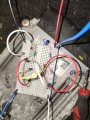
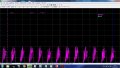
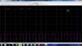
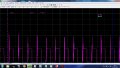
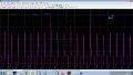
Right, I've built the circuit from post #26. Input and output shown in attachments. Unfortunately still not triggering the rev counter. Actual.jpg is what I'm trying to reproduce - this has a 12v driving voltage. Only real difference I can see from actual and out-mod2 is that the actual is peaking at just over 30v whereas out-mod2 is around 25v. How can I increase the peak a bit more?
The simple thing to try is to boost the supply voltage to that circuit. see if 15 volts instead of 12 will do it. The drive voltage might also need to be increased.
 Facebook
 Google
 GitHub
 Linkedin