 Facebook
 Google
 GitHub
 Linkedin
Hello,
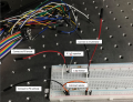
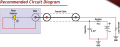
I am trying to follow the recommended circuit diagram of the photodiode I am using, as specified by its manual. Does the circuit below match the one in the diagram?
I am trying to follow the recommended circuit diagram of the photodiode I am using, as specified by its manual. Does the circuit below match the one in the diagram?
Attachments
-
 529.2 KB Views: 27
 -
 86.4 KB Views: 30


