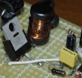
Circuit modification for lead battery desulphator

Dodgydave

Joined Jun 22, 2012
11,395
Are your AAC pages orange or blue? This site has two schemes. The orange is the default. In my experience, the orange scheme is not as forgiving as the blue scheme. I use the blue scheme. Fortunately, the site allows you to pick which one to use. Perhaps using the other scheme will let you do what you need to do.

So which do you use?

Knowing that, we may be able to help you change your settings and see if that helps. BTW, what OS and browser (including version) are you using!
How do you get the Blue site?
 

ronv

Joined Nov 12, 2008
3,770
Thanks for pointing that out. Yes, the idea of "Putative circuit Version 1" is to use the circuit with an N-fet. The idea is to make use of the components I have since it would take a long time to get replacements.

With the original circuit at the top the pulses from 555 will also be between 12 and 24 Volts, shouldn't that mean the Q1 P-fet will always be off? Why is that not the case - is it something to do with the inductors pulling the drain down, and could the inductors in my putative circuit be rearranged so that Q2 will switch on and off?

As you can see, my understanding of the circuit is rather limited, sorry about that.
Here is one using your FET.
It needs a PNP transistor to invert the signal and a base resistor. The value of this is not critical.
The inductors may be a problem. Maybe you could find some ferrite cores in some scrap equipment and try to wind your own.

I didn't have the model for your regulator so I used a Zener diode fot the 12 volts, so ignore that part and use what you have.
upload_2019-5-18_17-51-25.png
 

Thread Starter

Bhante

Joined Dec 15, 2009
64
I have a couple of NPN transistors but no PNP. Am I right in believing I could substitute an NPN for Q2 by putting the transistor between output and V-, and R6 between output and V+?

The inductor is more of a problem, I am still looking for something I could use. The Ferrite bead on a power lead wouldn't work would it?
 

ronv

Joined Nov 12, 2008
3,770
I have a couple of NPN transistors but no PNP. Am I right in believing I could substitute an NPN for Q2 by putting the transistor between output and V-, and R6 between output and V+?

The inductor is more of a problem, I am still looking for something I could use. The Ferrite bead on a power lead wouldn't work would it?
The difficulty with the NPN is that the source of the FET and ground for the 555 are not the same, so it can't be turned off.
If you have access to any junk equipment thet might be a source for something that could be used for the inductors.
upload_2019-5-20_11-39-59.jpeg
 

bertus

Joined Apr 5, 2008
22,921
Hello,

I did some mods on the schematic:

Desulphator low side drive.png
I hope it will work.

It could be that the signal is now inverted.
This could be solved using a NPN transistor as inverter.

Bertus
 

ronv

Joined Nov 12, 2008
3,770
I have a couple of NPN transistors but no PNP. Am I right in believing I could substitute an NPN for Q2 by putting the transistor between output and V-, and R6 between output and V+?

The inductor is more of a problem, I am still looking for something I could use. The Ferrite bead on a power lead wouldn't work would it?
Hello,

I did some mods on the schematic:

View attachment 177829
I hope it will work.

It could be that the signal is now inverted.
This could be solved using a NPN transistor as inverter.

Bertus
Bertus, the problem is he only has the negative regulator to drop the 24 volts down to 12. I used the Zener because I was to lazy to download his model.

But here is something that kind of works. I'm not crazy about it because the 12 volts for the 555 is unregulated and it requires a third wire to the batteries.

upload_2019-5-21_9-45-51.png
 

Thread Starter

Bhante

Joined Dec 15, 2009
64
I'm not crazy about that circuit either I am afraid - I worry the spikes from my inverter will quickly destroy the 555.

I am currently exploring a different aspect. I haven't been able to locate any available torroid ferrite core, and if I don't have a usable inductor then the transistor is moot.

So my questions:
1. If L3 is blown through being under-rated for peak current, what else in the circuit is likely to be destroyed as a result? (Or in other words, if I use the inductor I have and hope for the best, what is the risk if it fails?)
2. If I increase the inductance from 330uH to 440uH, what effect will that have on the peak current and on the general functioning of the circuit? What about importance of saturation of the inductor? If the circuit is not perfect, that is OK as long as it gives a productive result, even if it is a little slower.
3. If the inductance value of L3 is changed, does anything else critically need to be changed?
4. What if I intentionally degrade the saturation of L3 to reduce peak current (and the risk of blowing it), and how best to do that?

Last time I was overseas I got 2 each of L1, L2 and L3 (or rather, the inductors with ostensibly those values, although the rating of the L3 inductors is dubious; L2 is for the 12V version). Today I removed the heat shrink from L2 and L3, and the results are shown here (L3 - 330uH on top, L2 - 220uH bottom).

20190522_175606a.jpg

The difference in wire diameter can be seen very clearly. The 330uH has wire approximately 0.14mm diameter (7 turns per mm), and I estimate approximately 100 turns (approximately 3 layers). The 220uH has wire approximately 0.3mm diameter (3 turns per mm or fractionally over), and I estimate about 60 turns (3 layers plus 6 turns).

Using two of the 220uH inductors in series gives 440uH - my assumption is that that will reduce the peak current slightly (more importantly though perhaps is the effect on the operation of the circuit as a whole, about which I have to defer to experts!) Perhaps also the circuit would then not fully saturate L3 resulting in further reduction of peak current???

More importantly though, it is quite clear from the photo that L2 has much thicker wire, and can carry significantly more peak current than L3.


Further information that might be useful: in the pdf attached to my original post it gives a digikey part number suitable for L3, which gives more detailed specifications of the rating. The digikey link is here:
https://www.digikey.com/products/en?keywords=dn4518-nd
(Mouser part number 807-4590-334K )
This gives the following specification for a part that is known to perform well (4590 series made by API Delevan): maximum DC current 1.61A, 0.257 Ohms DC resistance, 0.95A current saturation, dimensions 23mm max x 11.5mm max, max power dissipation at 85C 0.7W (spec available from the link).
 

Thread Starter

Bhante

Joined Dec 15, 2009
64
Are you assuming I am using the 440uH, or the 330uH? Don't forget the 330uH that I have has only a QUARTER the cross-section area of the 440uH, therefore will blow very much sooner. Is there any way of calculating the current it will handle on the basis of the cross-sectional area, or will that be complicated by the degree of saturation?

If the change in inductance from 330uH to 440uH is too drastic, the other possibility would be to rewind ONE of the 220uH inductors with half the turns, making 110uH, and use that in series with the other 220uH to make 330uH. Is that correct? (Sorry if that is a stupid question, but it is nearly 50 years since I learnt about inductors!)

Regarding your simulation graphics, I assume the pulse at the top is the output from M1, and the other two are the current in the two inductors calculated from it? Where does the 9V pulse height come from (input pulse as opposed to output pulse??) According to the original article, the pulse across the battery may be initially as much as 50V for the 12V version (i.e. presumably 100V for the 24V version), and depends on the degree of sulphation of the battery.

In the meantime I've managed to find a PNP transistor, an 8550, so I should be able to go if I can resolve the inductor.
 
Last edited:

ronv

Joined Nov 12, 2008
3,770
Are you assuming I am using the 440uH, or the 330uH? Don't forget the 330uH that I have has only a QUARTER the cross-section area of the 440uH, therefore will blow very much sooner. Is there any way of calculating the current it will handle on the basis of the cross-sectional area, or will that be complicated by the degree of saturation?

If the change in inductance from 330uH to 440uH is too drastic, the other possibility would be to rewind ONE of the 220uH inductors with half the turns, making 110uH, and use that in series with the other 220uH to make 330uH. Is that correct? (Sorry if that is a stupid question, but it is nearly 50 years since I learnt about inductors!)

Regarding your simulation graphics, I assume the pulse at the top is the output from M1, and the other two are the current in the two inductors calculated from it? Where does the 9V pulse height come from (input pulse as opposed to output pulse??) According to the original article, the pulse across the battery may be initially as much as 50V for the 12V version (i.e. presumably 100V for the 24V version), and depends on the degree of sulphation of the battery.

In the meantime I've managed to find a PNP transistor, an 8550, so I should be able to go if I can resolve the inductor.
Bhante,
I haven't forgotten you. I'm just out of ideas.
The problem with the inductors is that the core saturates and when that happens it starts ot just look like a piece of wire, so the current goes way up.
 

Thread Starter

Bhante

Joined Dec 15, 2009
64
I got the replacement parts I needed on an overseas trip and have built the circuit. I connected it and all seemed well at first. After 10 or 15 minutes I noticed signs of a burning smell, and found the circuit was overheating, with some signs of smoke. There was light sparking at the terminal as I disconnected it (identical to when first connecting it), implying it is still functioning normally apart from overheating.

I tested the temperature of different components with my finger a couple of minutes or so after disconnecting. The resistor R4 was cold despite the black colour (but being small would have cooled down very quickly). Capacitor C5 was burning hot (the hottest component at that time). Both inductors were quite hot, especially L3. The only other hot components were Q1 (less hot than L3, ) and D1 (least hot, entirely normal). There was visible spoiling of L3, i.e. some kind of resin/flux/varnish or something bubbling out of the coil (hard and brittle when cold). See the photo.

I tried connecting again just now to see the temperatures sooner after disconnecting. After about a minute R4 was suddenly very very hot (slight puff of smoke even), but the other components were all below blood temperature.


I have a few questions.

1) Why should R4 get so hot? This is obviously a malfunction.

2) Why is C5 gettingvery hot?

3) As to the inductors, is this excessive or not? Maybe the observed temperatures is reasonably normal. What about the exudation?


Added 3/8:
As to the temperature of the inductors, I assume this would be due to slight saturation of the coil? If so, maybe it would be a good precaution to change the R1 and R2 to shorten theon time of Q1?

Nevertheless it seems to me the most serious problems are (1) and (2), which seem to reflect a defect somewhere ...

I am baffled why there should be so much current on the 555 side, which must be going through the 555 itself. Some kind of positive feedback loop going through R4/C3, C5 and U2 (via 555 pins 3-4)?

The circuit is generating pulses at the output which can be up to 50V according to the author. Could there be an AC current flowing through C5, U2, 555 pins 4-3, R4/C3, and Q1?
 

Attachments

Last edited:

ronv

Joined Nov 12, 2008
3,770
I got the replacement parts I needed on an overseas trip and have built the circuit. I connected it and all seemed well at first. After 10 or 15 minutes I noticed signs of a burning smell, and found the circuit was overheating, with some signs of smoke. There was light sparking at the terminal as I disconnected it (identical to when first connecting it), implying it is still functioning normally apart from overheating.

I tested the temperature of different components with my finger a couple of minutes or so after disconnecting. The resistor R4 was cold despite the black colour (but being small would have cooled down very quickly). Capacitor C5 was burning hot (the hottest component at that time). Both inductors were quite hot, especially L3. The only other hot components were Q1 (less hot than L3, ) and D1 (least hot, entirely normal). There was visible spoiling of L3, i.e. some kind of resin/flux/varnish or something bubbling out of the coil (hard and brittle when cold). See the photo.

I tried connecting again just now to see the temperatures sooner after disconnecting. After about a minute R4 was suddenly very very hot (slight puff of smoke even), but the other components were all below blood temperature.


I have a few questions.

1) Why should R4 get so hot? This is obviously a malfunction.

2) Why is C5 gettingvery hot?

3) As to the inductors, is this excessive or not? Maybe the observed temperatures is reasonably normal. What about the exudation?


Added 3/8:
As to the temperature of the inductors, I assume this would be due to slight saturation of the coil? If so, maybe it would be a good precaution to change the R1 and R2 to shorten theon time of Q1?

Nevertheless it seems to me the most serious problems are (1) and (2), which seem to reflect a defect somewhere ...

I am baffled why there should be so much current on the 555 side, which must be going through the 555 itself. Some kind of positive feedback loop going through R4/C3, C5 and U2 (via 555 pins 3-4)?

The circuit is generating pulses at the output which can be up to 50V according to the author. Could there be an AC current flowing through C5, U2, 555 pins 4-3, R4/C3, and Q1?
My guess is the FET is shorted. That would explain all but c3.
 
Top