 Facebook
 Google
 GitHub
 Linkedin
Hello. Fowllowing the discussion here and while I'm waiting for my UV LEDs, I'm using the time, to build at least 2 white LED light sources to use with my small USB microscope, because the LEDs that comes with the microscope, reflect a lot in the components under observation. So, using external light source, might improve the experience with reduced reflection from the LEDs, by controlling the angle of the LED light external sources.
We spoke about using a constant current source to provide constant current to the LEDs and have the best match regarding the light each LED will provide.
I want to ask a couple of things regarding the circuit I want to use to feed the LEDs.
I came up with the following circuit (file attached):

I started by setting the LEDs current to 60mA, 20mA to each one, as they are rated at 30mA.
But I think I'm not doing this correctly and I want to know where I am going wrong.
So, knowing that I'm using a 12V PSU and:
\(
\displaystyle{V_{LED}=5V}
\)
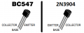
I'm using a BC548B with the following characteristics given by those Chinese transistor analysers:
hFE = 311
Vbe = 0.666V
9V Zener reverse bias Voltage
I would start by writing that:
\(
\displaystyle{I_{E} = \left (\beta + 1\right )\cdot I_{b}}
\)
\(
\displaystyle{I_{Load} = I_{C} = \left (\beta + 1\right )\cdot I_{b}}
\)
\(
\displaystyle{I_{Load} = \beta \cdot \frac{V_{E}}{\left (\beta + 1 \right )\cdot R_{E}} }
\)
\(
\displaystyle{I_{Load} = \frac{V_{b} - 0.666}{R_{E}}}
\)
So, the Emitter resistance would be:
\(
\displaystyle{R_{E} = \frac{V_{b} - 0.666}{I_{Load}}}
\)
Emitter resistance would be
\(
\displaystyle{R_{E} = \frac{9V - 0.666}{60mA} = 140.56Ω}
\)
for a 9V zener.
I'll keep going with the rest of the math, while I wait for confirmation!
We spoke about using a constant current source to provide constant current to the LEDs and have the best match regarding the light each LED will provide.
I want to ask a couple of things regarding the circuit I want to use to feed the LEDs.
I came up with the following circuit (file attached):
I started by setting the LEDs current to 60mA, 20mA to each one, as they are rated at 30mA.
But I think I'm not doing this correctly and I want to know where I am going wrong.
So, knowing that I'm using a 12V PSU and:
\(
\displaystyle{V_{LED}=5V}
\)
I'm using a BC548B with the following characteristics given by those Chinese transistor analysers:
hFE = 311
Vbe = 0.666V
9V Zener reverse bias Voltage
I would start by writing that:
\(
\displaystyle{I_{E} = \left (\beta + 1\right )\cdot I_{b}}
\)
\(
\displaystyle{I_{Load} = I_{C} = \left (\beta + 1\right )\cdot I_{b}}
\)
\(
\displaystyle{I_{Load} = \beta \cdot \frac{V_{E}}{\left (\beta + 1 \right )\cdot R_{E}} }
\)
\(
\displaystyle{I_{Load} = \frac{V_{b} - 0.666}{R_{E}}}
\)
So, the Emitter resistance would be:
\(
\displaystyle{R_{E} = \frac{V_{b} - 0.666}{I_{Load}}}
\)
Emitter resistance would be
\(
\displaystyle{R_{E} = \frac{9V - 0.666}{60mA} = 140.56Ω}
\)
for a 9V zener.
I'll keep going with the rest of the math, while I wait for confirmation!
Attachments
-
836 bytes Views: 5


")


