Facebook
 Google
 GitHub
 Linkedin

Hi everyone.
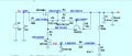
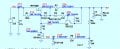
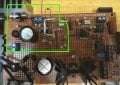
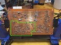
I finally finish the circuit I asked about some days ago. This time I have been carefull and I think there are no typos and I have labeled each component. It is part of a triode tester and this is the power supply for the anode/plate. It is supposed to give 0 to 300V.
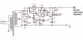
The problem is, it only gives 0 to 181V. Since is inside a cage, I have removed the PCB to run some tests. These tests have been made with 230V instead 300V because the 300V transformer is inside the cage and It is difficult to do the tests in that way. Some results:
- It keeps giving 181V maximum, no matter if I ran it with 300V or 220V
- At low voltages, R1 gets very hot. It is rated 1 watt
- D6 have a voltage drop of 0,028V
- The original potentiometer was 200K but mine have 180k. I have made new tests with a 220k potentiometer and It goes to 211V
- I repeated the test with 250V and only goes up to 213V output
I suffer from severe ADHD and my first idea was I made a bad connection, but I have checked all the connections 3 times following then in the PCB and marking on the printed image of the circuit to be sure and everything looks fine.
I´m clueless about this. Could anyone help me?
I finally finish the circuit I asked about some days ago. This time I have been carefull and I think there are no typos and I have labeled each component. It is part of a triode tester and this is the power supply for the anode/plate. It is supposed to give 0 to 300V.
The problem is, it only gives 0 to 181V. Since is inside a cage, I have removed the PCB to run some tests. These tests have been made with 230V instead 300V because the 300V transformer is inside the cage and It is difficult to do the tests in that way. Some results:
- It keeps giving 181V maximum, no matter if I ran it with 300V or 220V
- At low voltages, R1 gets very hot. It is rated 1 watt
- D6 have a voltage drop of 0,028V
- The original potentiometer was 200K but mine have 180k. I have made new tests with a 220k potentiometer and It goes to 211V
- I repeated the test with 250V and only goes up to 213V output
I suffer from severe ADHD and my first idea was I made a bad connection, but I have checked all the connections 3 times following then in the PCB and marking on the printed image of the circuit to be sure and everything looks fine.
I´m clueless about this. Could anyone help me?
Last edited: