Circuit Design Tip

Thread Starter

Exjay

Joined Nov 19, 2015
196
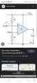
I don't know if this question is in the right topics section. However, I believe circuit Design cuts across all fields in electronics. My question is this: Why can't I use resistors in other ranges for design? To make my question clearer, let's look at an op amp comparator circuit. I understand the circuit operation but I find it difficult as how they arrive at those resistors values. Can't we use 10ohms instead of 10k ohms for example in biasing the non inverting pin using voltage divider? Please any explanation should reference designing from a datasheet. Thanks
 

BobTPH

Joined Jun 5, 2013
11,515
You can, but it would waste lot of power.

To continue the same discussion, why not 10MΩ?

Because the input draws some small current, say 1uA. This is called the input bias current, and should be in the datasheet. In a 10 K resistor this would result in a drop of 0.01V. That is probably acceptable. But 10M would drop 10V. That is not acceptable, it would ruin the bias.

All design is trade-offs and compromise.
 

ZCochran98

Joined Jul 24, 2018
351
The choice of range for certain component values usually comes down to one or several of a number of factors:
  • Component availability (which is why you'll often see 4.7k ohm rather than something like 4.5k - not to say 4.5k ohm DOESN'T exist; it just isn't a standard resistance, as an example)
  • Power handling capability. For instance, if you have a voltage divider and you want to split voltage in half, you COULD use two 1-ohm resistors, but you could ALSO use two 1 M ohm resistors. The 1-ohm resistors will have more current passing through them, though, resulting in a much higher power dissipation, which can destroy the resistor.
  • Power consumption. Again, back to the voltage divider example, if your power supply is rated at 10W and is a 10V supply, then, at most, you can draw 1A of DC current. The divider based on the 1-ohm resistor will pull 1/2 W in purely dissipated power, while the one based on the 1 M ohm resistor will dissipate only 1/2 uW.
  • Impedance matching. Sometimes you want to match to an input/output impedance to maximize power transfer, so you have no choice on what components you use. Sometimes you want as HIGH as a resistance as possible (like on the input of a voltage amplifier), and sometimes you want it as LOW as possible (like on the output of a voltage amplifier).
  • Delay constants or "because the math said so." In some cases, like anything based on timing, the component values required to achieve certain design parameters is required.
  • "Because the datasheet said so." Also a common explanation - you assume (perhaps wisely, perhaps foolishly) that the people who made the datasheet had optimized the example circuit in the datasheet for something. Some may even give you specific part numbers to find. Filters and power regulators and designs that use them tend to follow this methodology.
  • Completely arbitrarily. Sometimes designers throw down values because "it just looks right." These values are sometimes just "guessed" through instinct, prior experience, or any number of reasons. Perhaps some values they use had a reason once upon a time, but the designer hasn't bothered to investigate why. This is frequently related to the "because the datasheet said so" explanation. Voltage regulators also tend to follow this methodology when choosing filter capacitors (and if the designer doesn't want to sit down and perfectly optimize the capacitor choice).

In the example you gave, the 10 kOhm resistor is used for a few reasons. First, from a power-handling reason. You don't want your parts burning up, so if your circuit just relies on ratios of things, then use a larger "base value." It sometimes can get excessive, especially when you need higher current draw for something, but the kOhm range is a good starting point.

Furthermore, that op-amp may also have some bandwidth or cutoff frequency that is controlled, to some degree, with external resistors, especially when coupled with the input capacitance of the chip. You could reduce the resistance to increase the bandwidth towards it theoretical max, but then you start getting back into the power-handling capability territory. This cutoff frequency contributes to, potentially, why the resistor is in the kOhm range and not the MOhm range.

In addition, larger your input resistor is, the closer it is to the input impedance of the amplifier, so the less voltage actually "makes it" across the amplifier terminals (because you've formed an unintentional voltage divider). The input resistance of an op-amp is typically reported on the datasheet. Output impedance of the amps also inform the scale.

Because op-amp amplification is controlled frequently by feedback, the feedback resistor needs to be sufficiently larger than the output impedance of the amp, so as to avoid the same resistor divider problem. This, again, typically pushes the value into the hundreds of Ohms, to kOhms and beyond. The need then for kOhm resistors on the feedback loop and a desired gain value then leads to an input resistor in the kOhm range as well.

These factors combined together are why 10 kOhm is used, as an example, as compared to 10 Ohm. Once you've designed enough and get an intuition for things, then you start relying on the "because it looks about right" method, if what you're doing doesn't need to be optimized. But even with experience, it's always good to go back and check assumptions and verify "why" certain values and ranges are chosen.

Hope this helps!
 

Thread Starter

Exjay

Joined Nov 19, 2015
196
Thanks but it looks abstract to me. I am reading a book on electronics basic circuit. I'm a newbie.
The choice of range for certain component values usually comes down to one or several of a number of factors:
  • Component availability (which is why you'll often see 4.7k ohm rather than something like 4.5k - not to say 4.5k ohm DOESN'T exist; it just isn't a standard resistance, as an example)
  • Power handling capability. For instance, if you have a voltage divider and you want to split voltage in half, you COULD use two 1-ohm resistors, but you could ALSO use two 1 M ohm resistors. The 1-ohm resistors will have more current passing through them, though, resulting in a much higher power dissipation, which can destroy the resistor.
  • Power consumption. Again, back to the voltage divider example, if your power supply is rated at 10W and is a 10V supply, then, at most, you can draw 1A of DC current. The divider based on the 1-ohm resistor will pull 1/2 W in purely dissipated power, while the one based on the 1 M ohm resistor will dissipate only 1/2 uW.
  • Impedance matching. Sometimes you want to match to an input/output impedance to maximize power transfer, so you have no choice on what components you use. Sometimes you want as HIGH as a resistance as possible (like on the input of a voltage amplifier), and sometimes you want it as LOW as possible (like on the output of a voltage amplifier).
  • Delay constants or "because the math said so." In some cases, like anything based on timing, the component values required to achieve certain design parameters is required.
  • "Because the datasheet said so." Also a common explanation - you assume (perhaps wisely, perhaps foolishly) that the people who made the datasheet had optimized the example circuit in the datasheet for something. Some may even give you specific part numbers to find. Filters and power regulators and designs that use them tend to follow this methodology.
  • Completely arbitrarily. Sometimes designers throw down values because "it just looks right." These values are sometimes just "guessed" through instinct, prior experience, or any number of reasons. Perhaps some values they use had a reason once upon a time, but the designer hasn't bothered to investigate why. This is frequently related to the "because the datasheet said so" explanation. Voltage regulators also tend to follow this methodology when choosing filter capacitors (and if the designer doesn't want to sit down and perfectly optimize the capacitor choice).

In the example you gave, the 10 kOhm resistor is used for a few reasons. First, from a power-handling reason. You don't want your parts burning up, so if your circuit just relies on ratios of things, then use a larger "base value." It sometimes can get excessive, especially when you need higher current draw for something, but the kOhm range is a good starting point.

Furthermore, that op-amp may also have some bandwidth or cutoff frequency that is controlled, to some degree, with external resistors, especially when coupled with the input capacitance of the chip. You could reduce the resistance to increase the bandwidth towards it theoretical max, but then you start getting back into the power-handling capability territory. This cutoff frequency contributes to, potentially, why the resistor is in the kOhm range and not the MOhm range.

In addition, larger your input resistor is, the closer it is to the input impedance of the amplifier, so the less voltage actually "makes it" across the amplifier terminals (because you've formed an unintentional voltage divider). The input resistance of an op-amp is typically reported on the datasheet. Output impedance of the amps also inform the scale.

Because op-amp amplification is controlled frequently by feedback, the feedback resistor needs to be sufficiently larger than the output impedance of the amp, so as to avoid the same resistor divider problem. This, again, typically pushes the value into the hundreds of Ohms, to kOhms and beyond. The need then for kOhm resistors on the feedback loop and a desired gain value then leads to an input resistor in the kOhm range as well.

These factors combined together are why 10 kOhm is used, as an example, as compared to 10 Ohm. Once you've designed enough and get an intuition for things, then you start relying on the "because it looks about right" method, if what you're doing doesn't need to be optimized. But even with experience, it's always good to go back and check assumptions and verify "why" certain values and ranges are chosen.

Hope this helps!
 

AnalogKid

Joined Aug 1, 2013
12,129
The image you posted is a concept drawing of a comparator circuit, not a full-fledged design schematic. It shows the comparator's reference input as 50% of Vcc, but sinde there is nothing about the input signal voltage range, this is meaningless.

The basic operation is that when Vin is greater than Vref, the output stage of the comparator or opamp is saturated at its highest possible output voltage, sometimes called a "logic high". When Vin is less than Vref, the output is saturated at its lowest possible output voltage, a logic low. There are a lot of variations on how this works in the real world, but without part numbers and component values all we can do is discuss theoreticals.

ak
 

WBahn

Joined Mar 31, 2012
32,834
Pls explain with this diagram
1687385556024.png

In an ideal world, you could use a 1 Ω resistor or a 100 MΩ resistor for R.

But let's look at the consequences in the real world.

If R = 1 Ω and Vcc = 10 V, then the power supply has to deliver 5 A of current just to support these two resistors that only serve the purpose of setting Vref, the inverting input of the opamp/comparator, to Vcc/2.

On paper, so what? But in the real world, most supplies that would likely be used are not capable of doing that, not to mention being able to do it while maintaining Vcc at the desired voltage and while supplying power to everything else in the circuit, not to mention having to deal with the heat given off from the 25 W of power being dissipated in each resistor.

So, to address these issues, you want R to be as big as possible. Looked at another way, there is a minimum value for R that is acceptable from the standpoint of current draw and power requirements.

What about using 100 MΩ resistors? That would only draw 50 nA of current and each resistor would only be dissipating 250 nW of power. Sounds pretty good... on paper.

But no opamp/comparator is ideal and the circuitry inside the chip does require some current to flow into or out of each input in order to operate properly. This is known as the input bias current. For instance, for the LM324, the input bias current is typically about 10 nA but can be as high as 60 nA.

Let's say that it is the typical 10 nA (flowing out of the pin), What would Vref be? It would end up at 4.5 V 2.0 V instead of the intended 5.0 V 2.5 V. What if it was closer to the upper limit of 60 nA? At that point it would be all the way down to 2 V. If you were to use much larger resistors, you would reach a point where you couldn't even support the bias current and there is no telling how the device would behave.

Other factors that place upper limits on the value of R are noise-related. The larger R is, the more noise it generates and the more sensitive it is to electromagnetic interference.

So these place a maximum value for R that is acceptable from these standpoints.

This often results in an allowable range of values for R that is still pretty large and the designer is free to pick any values within the range, often choosing something that is somewhere in the middle of the min and max in order to achieve a strong compromise between all the competing issues. In this example, that range might be from 10 kΩ to 1 MΩ and a designer might choose to use 100 kΩ resistors.

EDIT: Made a mental error in calculating Vref with the 10 nA bias current. Corrected above.
 
Last edited:

Thread Starter

Exjay

Joined Nov 19, 2015
196
View attachment 296858

In an ideal world, you could use a 1 Ω resistor or a 100 MΩ resistor for R.

But let's look at the consequences in the real world.

If R = 1 Ω and Vcc = 10 V, then the power supply has to deliver 5 A of current just to support these two resistors that only serve the purpose of setting Vref, the inverting input of the opamp/comparator, to Vcc/2.

On paper, so what? But in the real world, most supplies that would likely be used are not capable of doing that, not to mention being able to do it while maintaining Vcc at the desired voltage and while supplying power to everything else in the circuit, not to mention having to deal with the heat given off from the 25 W of power being dissipated in each resistor.

So, to address these issues, you want R to be as big as possible. Looked at another way, there is a minimum value for R that is acceptable from the standpoint of current draw and power requirements.

What about using 100 MΩ resistors? That would only draw 50 nA of current and each resistor would only be dissipating 250 nW of power. Sounds pretty good... on paper.

But no opamp/comparator is ideal and the circuitry inside the chip does require some current to flow into or out of each input in order to operate properly. This is known as the input bias current. For instance, for the LM324, the input bias current is typically about 10 nA but can be as high as 60 nA.

Let's say that it is the typical 10 nA (flowing out of the pin), What would Vref be? It would end up at 2.0 V instead of the intended 2.5 V. What if it was closer to the upper limit of 60 nA? Now you couldn't even support the bias current and there is no telling how the device will behave.

Other factors that place upper limits on the value of R are noise-related. The larger R is, the more noise it generates and the more sensitive it is to electromagnetic interference.

So these place a maximum value for R that is acceptable from these standpoints.

This often results in an allowable range of values for R that is still pretty large and the designer is free to pick any values within the range, often choosing something that is somewhere in the middle of the min and max in order to achieve a strong compromise between all the competing issues. In this example, that range might be from 10 kΩ to 1 MΩ and a designer might choose to use 100 kΩ resistors.
I like your explanation but I'm trying to figure out how you got 2.0v.
 

WBahn

Joined Mar 31, 2012
32,834
There's a comparator circuit there but not the same configuration as this.
So?

The circuit you gave does one thing -- outputs either ~0 V or ~Vcc depending on whether the input voltage is above or below Vcc/2.

The circuit on page 6 does something else -- it is a free-running oscillator circuit that automatically cycles back and forth between ~0 V and ~Vcc periodically.

Not surprising that two circuits that do different things are different.
 

WBahn

Joined Mar 31, 2012
32,834
I like your explanation but I'm trying to figure out how you got 2.0v.
Actually, I made a mistake because I was doing the math in my head and I subtracted the 0.5 V error from 2.5 V (half of 5 V) instead of from 5.0 V (half of 10 V). So it should have been 4.5 V.
 

Thread Starter

Exjay

Joined Nov 19, 2015
196
Thanks for your reply. Can you explain how the bias current affects your calculations?
Actually, I made a mistake because I was doing the math in my head and I subtracted the 0.5 V error from 2.5 V (half of 5 V) instead of from 5.0 V (half of 10 V). So it should have been 4.5 V.
 

WBahn

Joined Mar 31, 2012
32,834
Thanks for your reply. Can you explain how the bias current affects your calculations?
Just apply KCL at the Vref node.

If Io is the bias current flowing out of the non-inverting input of the opamp/comparator, then KCL is:

(Vcc - Vref)/R = Vref/R + Io

Solve for Vref.

Vref = Vcc/2 - Io·R/2

The first term is the nominal Vref and the second is the error due to the input bias current.

Let's say that your Vcc is regulated to 1% and you are using 1% tolerance resistors and so you want to limit the error term to a comparable level. What constraint does that place on R?

This means that you want the error term to be less than 1% of the nominal Vref at the maximum value of the bias current, or

Io·R/2 < 1%·Vcc/2

R < 1% · (Vcc/Io) = 0.01·(10 V / 60 nA)
R < 0.01 · (10 V / 60 nA)
R < 1.67 MΩ
 

jiggermole

Joined Jul 29, 2016
185
Just apply KCL at the Vref node.

If Io is the bias current flowing out of the non-inverting input of the opamp/comparator, then KCL is:

(Vcc - Vref)/R = Vref/R + Io
I gotta go back to the books. Its been way too long since I used Kirchoffs Current Laws. Basic DC still kicks my butt. And especially how it applies to the magic dorito of op-amps.
 

WBahn

Joined Mar 31, 2012
32,834
I gotta go back to the books. Its been way too long since I used Kirchoffs Current Laws. Basic DC still kicks my butt. And especially how it applies to the magic dorito of op-amps.
You definitely need to get the basic analysis concepts and skills down cold. If not, they will haunt you incessantly.
 
Top