Chinese time on-delay board being naughty.

Thread Starter

boydage

Joined Oct 7, 2016
92
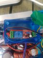
Have setup a solar inverter to run a small fridge. Not wanting my large inverter to be running full time draining power, I have disconnected the wires to the thermostat, utilised the input/output with 12vdc to control 2 relays.

RL1 = inverter on/off function
RL2 = power to a larger SSR (pictured)
SSR = 230v to the compressor.

RL2 is a small Chinese time on delay board in the pic. Means the inverter can have time to come up to voltage prior to the fridge powering on. Only problem, and is apparent in both boards I have here is I can hear the relay cycling, clicking rapidly off/on.........................off/on....... Occasionally this is evident on the LED on the SSR.

First thought is the fridge thermostat is designed for 230vac and the 12vdc I am running though it is only just making enough to make the relay but I have 13.1vdc on the input to the relay. So am unsure why.

Any ideas? I was thinking I might put a cap accross the input to RL2. ??
 

Attachments

Thread Starter

boydage

Joined Oct 7, 2016
92
Hi. No. No schematic for the board. I put a 3300uf cap across the input to the board earlier. It seemed to smooth it out, took away the undecidedness and the clicking has gone. I guess I should run it for a day to see if that actually was the resolution? I am wondering if the 12vdc through the fridges thermostat was too dirty?
 

ericgibbs

Joined Jan 29, 2010
18,849
hi boydage,
Are you running the units in the way they are shown in the photo.?? ie: laid on top of the SMPS.
The SMPS will be radiating electrical noise.
E
 

Reloadron

Joined Jan 15, 2015
7,517
What you have seems similar to this board which I have also seen on Amazon in a two package deal. The fact that you have two boards displaying the same behavior is peculiar. Unless as Eric mentions due to positioning there is interference they should work. All of the boards like this I have seen from China, delay on make, energize the relay a period after 12 VDC is applied and they all use a 555 timer chip with a basic and obvious RC timing network. Something to try is adjust the potentiometer close to fully clockwise. Just power the board from a 12 VDC source like the battery in a car or truck or the utility 12 VDC outlet in a car or truck. Something with a nice clean DC power. See iof it works?

Ron
 

Thread Starter

boydage

Joined Oct 7, 2016
92
Hi. Yes, currently operating it as the picture is showing, I began to run out of time, with the fact its only going to be used 2 weeks a year its not pretty.

Both of the boards do work correctly, and energize the SSR after about 25 seconds. It is after approx 60 seconds that the board starts to cycle off/on.

The power for this control circuit comes directly off the 12vdc battery input to the inverter. Interesting to hear the SMPS might be interfering with the board? Whats a SMPS? Ha

So I have put a cap across the input to the board, and it seems to have taken away the problem. So I guess I leave it like this?
 

Attachments

Thread Starter

boydage

Joined Oct 7, 2016
92
Thanks Ron. I should have just looked. Ok well the cap I installed was all I needed to do. Still running, no longer cycling. Rgds Boydage
 

MisterBill2

Joined Jan 23, 2018
18,508
It may also be that the time delay circuit board is voltage sensitive and the voltage was dropping after a bit.
Was there a problem with the refrigerator compressor starting with a direct connection to the inverter?
 

Thread Starter

boydage

Joined Oct 7, 2016
92
Hi. I actually have the delay relay powering a SSR so it is not directly connected to the compressor. I decided to draw it up, but am shocking at drawings - (couldnt even find a symbol for the compressor motor). But attached so you get the drift.

But I can say now its been operating for several days now without any worries. Its a reasonably sized fridge too. So am having to add a section to my trailer to take it camping....... hahha
 

Attachments

MisterBill2

Joined Jan 23, 2018
18,508
OK, A universal symbol for a motor is a circle, with as many connections drawn in as the motor has wires. Labeling is the important part, so that the connections can be understood by others. There are free electrical drawing programs available, I have always been able to use the cad programs of my employer, on my own time.
Around here there may only be enough sun to make solar cells worth the effort for a few weeks during the summer. So good luck, now that you have the system working.
 
Top