Charge at 24v and Discharge at 48v

Thread Starter

Sinix

Joined Sep 24, 2024
2
Hey guys,

I´m trying to accomplish a system where it charges at 24 volts and discharges at 48 volts simultaneously.
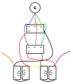
There is a diagram in attachment.
I have a 3 phase generator that it´s connected to 2 Full Bridge Rectifiers.
I have 4x 12v batteries, 2 connected in series to make 24 volt batteries.
Each 24 volt battery pack is connected to its own rectifier.
This is to Charge at 24 Volts.

Now, the tricky part! How to Discharge at 48V?
The yellow wire makes it a 48 volt battery. The Purple wire is the Positive 48V and the Orange wire is the Negative 48v.

Is such a thing simultaneously possible?

Cheers
 

Attachments

dl324

Joined Mar 30, 2015
18,405
Welcome to AAC!
I´m trying to accomplish a system where it charges at 24 volts and discharges at 48 volts simultaneously.
Assuming the 12V batteries are lead acid, they're going to require a voltage higher than 24V to charge each pair of batteries. That means the load expecting 48V is going to see something more like 55V.

Can't give a more detailed response because you didn't give information about the load current, charging current, or battery capacity.

I'm assuming that the charging circuits are simplifications because you'll need circuitry to adjust the charging voltage based on state of charge. In more complete solution, you'll probably want something that monitors the voltage of each battery to make sure a weak one doesn't fall victim to a stronger one. This assumes the load can tolerate 55V (plus with lead acid batteries, 48V is going to be more like 50V).
 

crutschow

Joined Mar 14, 2008
38,578
To charge the two 24V batteries while they are connected in series will require that at least one of the charging circuits isolated from common which you circuit does not do.
Also the charging circuits will need some sort of regulator to control the charging voltage and limit the current.
 

dendad

Joined Feb 20, 2016
4,641
AAC_48V.jpg
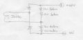
You can use a basic Voltage Doubler circuit but have your batteries replacing the capacitors that are normally used. This is a single phase setup but it could work with a 3 phase Y connection and 6 diodes, but not with a Delta connection. Note that a 24VAC supply will try to charge to about 68V eventually. You would really do better to get an intelligent 48V battery charger to help protect your batteries as it is easy to kill them. Whatever your generator and batteries are, some control system is needed.
More info is really needed. What voltage is your generator, and the battery chemistry? This is important.
EDIT: As @crutschow mentions above, the supply will need to be isolated from anything else, no common connection.
 

Thread Starter

Sinix

Joined Sep 24, 2024
2
Thanks for the replays fellas.
The voltage is being monitored and controlled by an ESP8266. But that is not the question from the OP.
Guys please just stick to the OP question.
By following the diagram in the rectifiers, how can it be shorted, if it blocks the flow from positive to negative?
Why does it work with controllers but not with Full Bridge Rectifiers?
What am I missing?

Cheers
 

dendad

Joined Feb 20, 2016
4,641
Draw out the circuit showing the diodes in the rectifiers.
Also, answer the questions asked too as they are important.
And, how is the voltage monitored and controlled by the ESP8266? It does really help for you to show all the details!
 

crutschow

Joined Mar 14, 2008
38,578
What am I missing?
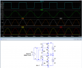
The short circuit between the two bridges since they are connected in series.
The sim below shows the short circuit current path through D2, D4, D5, and D7.
Note that the source V2 voltage (blue trace) is shorted by two diodes in series for each half cycle.

1727219724639.png
 

LowQCab

Joined Nov 6, 2012
5,101
Is such a thing simultaneously possible?
.
The short answer is "NO".
.
The "24-Volt-Batteries" can be placed in parallel for maximum Current,
then run through a 24 to 48-Volt-Inverter.
The practicality, and most importantly, the expense, of such an arrangement will
depend on how much Peak-Current You need at ~48-Volts.
.
.
.
 

MisterBill2

Joined Jan 23, 2018
27,741
A "cheating trick would be to do a capacitor isolation in both AC connections to one of the bridge rectifiers. Certainly without that you have a THREE diode in series short circuit across the transformer. Different diodes in the short circuit for each half of the sine wave.
A second scheme will be to use the transformer to feed a VOLTAGE DOUBLER circuit, and then you could have enough voltage to charge both batteries in series. The compromise will be only half as much charging current available. But it would work.
 
Top